Description
A comprehensively engineered Submerged Arc Furnace (SAF) for silicomanganese production — purpose-built for high-yield, energy-efficient ferroalloy smelting with industry-leading manganese recovery rates.
Overview — The Role of the Silicomanganese Furnace in Modern Ferroalloy Smelting
The Silicomanganese Furnace is a specialized type of submerged arc furnace designed exclusively for the carbothermic production of silicomanganese (Si-Mn) alloy — a critical input material for the global steelmaking industry. As a core piece of equipment in ferroalloy smelting, this furnace converts oxidic manganese-bearing raw materials into a high-value liquid alloy under precisely controlled conditions of temperature, reductant stoichiometry, and electrical load.
In the broader landscape of ferroalloy smelting, silicomanganese occupies a unique position. It simultaneously delivers both silicon (typically 15–20%) and manganese (65–70%) into the molten steel bath, replacing the older practice of adding separate high-carbon ferromanganese and ferrosilicon. A properly designed SAF for silicomanganese achieves this dual-function metallurgical outcome in a single production step, thereby reducing total energy consumption per ton of steel deoxidized and alloyed.
From a process engineering standpoint, a Silicomanganese Furnace must operate at significantly higher temperatures than a standard ferromanganese furnace — typically 1600 °C to 1650 °C at the coke-bed reaction zone — in order to drive the endothermic silica reduction reaction (SiO₂ + 2C → Si + 2CO) to completion. This thermal requirement places stringent demands on furnace lining refractories, electrode management, and the electrical control system. Every SAF for silicomanganese must be engineered with these thermodynamic realities in mind, not simply scaled up from a ferromanganese design.
Metallurgical Principles and Thermochemical Basis
The production of silicomanganese alloy in a Silicomanganese Furnace proceeds through a multi-stage carbothermic reduction sequence. Understanding these reduction pathways is essential for proper furnace design and operational control in any ferroalloy smelting operation.
Core Thermochemical Reactions (occurring at 1300–1650 °C):
MnO₂ → Mn₂O₃ → Mn₃O₄ → MnO → Mn (staged manganese reduction)
SiO₂ + 2C → Si + 2CO(g) (silica reduction, ΔH ≫ 0, endothermic)
SiO₂ + 2SiC → 3Si + 2CO(g) (intermediate SiC-mediated pathway)
2(MnO) + Si ⇌ 2Mn + (SiO₂) (slag-metal equilibrium, R-ratio dependent)
The first two decomposition steps — MnO₂ to Mn₂O₃ (above 450–500 °C) and Mn₂O₃ to Mn₃O₄ (above 900–950 °C) — occur thermally without any carbonaceous reducing agent. Reduction of Mn₃O₄ to MnO, however, requires CO gas or solid carbon. The final reduction of MnO by carbon is only thermodynamically feasible above 1410 °C at atmospheric pressure, and practically requires even higher temperatures for commercially viable kinetics. This is why a well-engineered SAF for silicomanganese must maintain deep electrode penetration and a hot, active coke-bed zone.
The distribution of silicon between the alloy and the MnO-SiO₂-CaO-Al₂O₃-MgO slag system is governed primarily by process temperature, SiO₂ content of the slag, and the R-ratio defined as (CaO + MgO) / Al₂O₃. Research has established that Si equilibrium content in the alloy increases by approximately 6% for each 50 °C temperature increment in the 1550–1700 °C range. These fundamental relationships directly inform the design parameters of every Silicomanganese Furnace.
Complete Equipment System — Anatomy of a Silicomanganese Furnace
A Silicomanganese Furnace is not a standalone vessel — it is an integrated metallurgical system comprising multiple interdependent subsystems. In ferroalloy smelting, equipment reliability determines both throughput and alloy quality. The following are the major constituent assemblies:
Furnace Shell & Lining
Heavy-gauge welded steel shell with multi-layer refractory lining — magnesia-carbon bricks in the hot-face zone, high-alumina backup layers, and insulating boards. Circular design; a typical 40 MVA furnace features an external diameter of 11.6 m and a shell height of 6.2 m.
Electrode System
Three self-baking (Søderberg) electrodes arranged in a delta configuration, with hydraulic or electromechanical slipping and regulation. Electrode diameter scales with furnace rating — typically 1.2–1.6 m for 25–40 MVA units.
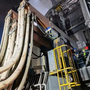
Short Network
High-current copper busbar assembly delivering power from the furnace transformer secondary terminals to the electrodes. Optimized geometry minimizes inductive reactance and ensures balanced three-phase power distribution.
Water Cooling System
Closed-loop deionized water circuits for electrode holders, contact clamps, pressure rings, furnace roof, and fume elbows. Includes temperature, flow, and pressure monitoring with automatic safety interlocks.
Charging & Feeding System
Overhead storage bins with automated weigh-batching, belt conveyors, and multiple charging chutes arranged around the electrode circles. Ensures uniform burden distribution and consistent electrode burial depth.
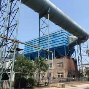
Fume Extraction & Gas Treatment
Fully enclosed furnace hood with water-cooled ducting, baghouse filtration (or electrostatic precipitator), and CO-rich off-gas recovery system suitable for power generation or preheating applications.
Tapping & Casting System
Refractory-lined taphole assembly with mud gun or drill, slag skimming launder, alloy granulation tank or pig-casting machine, and slag water-quenching circuit for by-product valorization.
Automation & Control
PLC/SCADA-based integrated control platform with real-time monitoring of electrode current, voltage, position, power factor, cooling water parameters, furnace pressure, and off-gas composition — enabling predictive process management.
Technical Specifications — Silicomanganese Furnace Series
The Silicomanganese Furnace product range spans from compact 9 MVA units suitable for smaller-scale ferroalloy smelting operations to large 40+ MVA installations designed for integrated steel-mill captive alloy production. Representative specifications are presented below.
| Parameter | 9 MVA | 16.5 MVA | 25 MVA | 33 MVA | 40 MVA |
|---|---|---|---|---|---|
| Furnace Type | Fixed, closed | Fixed, closed | Fixed, closed | Fixed, closed | Fixed, closed |
| Shell Diameter (m) | 6.5 | 8.2 | 9.6 | 10.5 | 11.6 |
| Shell Height (m) | 4.5 | 5.0 | 5.5 | 5.8 | 6.2 |
| Electrode Diameter (mm) | 780 | 950 | 1150 | 1350 | 1500 |
| Secondary Voltage (V) | 100–140 | 120–170 | 140–200 | 150–220 | 160–240 |
| Daily Output (t Si-Mn) | 45–55 | 85–100 | 130–150 | 170–200 | 200–240 |
| Annual Capacity (t) | 15,000–18,000 | 28,000–33,000 | 43,000–50,000 | 56,000–66,000 | 66,000–80,000 |
| Specific Power Consumption (kWh/t) | 3,800–4,500 | 3,700–4,300 | 3,600–4,200 | 3,500–4,000 | 3,500–3,900 |
| Mn Recovery Rate (%) | 82–87 | 83–88 | 84–89 | 85–90 | 86–92 |
| Electrode Consumption (kg/t) | 22–28 | 20–25 | 18–23 | 16–21 | 15–20 |
* Values are indicative and depend on raw material quality, slag practice, and operating discipline. All specifications are customizable to match specific site conditions, power availability, and production targets.
Production Process — From Raw Material to Finished Alloy
The operation of a SAF for silicomanganese follows a well-established sequence, refined through decades of industrial practice in ferroalloy smelting:
Raw Material Preparation & Proportioning
Manganese ore (Mn ≥ 30%, typically pyrolusite or psilomelane), quartzite (SiO₂ ≥ 97%, particle size 10–60 mm), metallurgical coke or anthracite (fixed carbon ≥ 80%, 10–25 mm), and fluxes (dolomite or limestone) are crushed, screened, dried to < 2% moisture, and batched by weight. A typical charge ratio of Mn ore to quartzite is approximately 1:0.20–0.30, adjusted continuously based on slag chemistry feedback. High-carbon Fe-Mn slag can be incorporated at up to 40% of the manganese unit input to improve impurity control and reduce specific energy consumption.
Charging & Burden Distribution
The prepared charge mix is conveyed to overhead day bins and fed into the Silicomanganese Furnace through multiple charging tubes arranged concentrically around each electrode. Uniform burden distribution is critical — uneven feeding causes electrode position asymmetry, unbalanced three-phase power, and localized overheating of the furnace lining. Modern SAF for silicomanganese installations employ automated charging logic linked to electrode current feedback.
Submerged Arc Smelting — The Core Stage
Electrical current passes from the electrode tips through the burden, generating heat via resistive (Joule) heating in the coke bed and micro-arcing at the electrode tips. Heat is governed by P = I²R, where R is the charge resistance. The electrode tips are maintained approximately 600 mm above the molten alloy bath. Three distinct zones form: (a) a preheating/pre-reduction zone (1100–1200 °C) where higher manganese oxides decompose and iron oxides are reduced to metallic iron; (b) the coke bed zone (1550–1650 °C) where liquid slag forms, MnO reduction nears completion, and silica reduction begins; (c) the molten alloy bath where liquid Si-Mn collects beneath the slag layer.
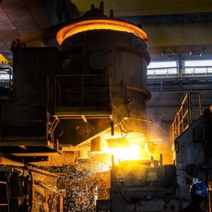
Tapping, Casting & Slag Handling
Tapping is performed at regular intervals (typically every 2–4 hours depending on furnace size) through a refractory-lined taphole. The alloy and slag are separated in a skimming launder. The molten Si-Mn alloy (typical composition: Mn 65–68%, Si 17–20%, C 1.5–2.0%, Fe balance) is cast into pigs, granulated, or directly transferred to ladle refining. Slag — containing 35–45% SiO₂ and ideally less than 5% MnO — is water-quenched and can be utilized as a construction aggregate or cement raw material. Effective slag management in ferroalloy smelting directly influences manganese recovery, which typically ranges from 85% to 92% depending on slag basicity and temperature control.
Off-Gas Treatment & Energy Recovery
The closed-top design of the Silicomanganese Furnace captures CO-rich off-gas (CO content typically 60–70%) which, after dedusting via baghouse or electrostatic precipitator, can be used to fire a waste-heat boiler for steam generation, preheat combustion air, or fuel a gas engine for on-site power generation. Dust collected in the filtration system is manganese-rich and can be pelletized and recycled back into the furnace charge, improving overall material efficiency.
Key Operational Control Parameters
Successful ferroalloy smelting in a Silicomanganese Furnace depends on disciplined control of the following variables. Deviations from optimal ranges rapidly translate into higher power consumption, lower manganese recovery, and off-specification alloy grades.
| Control Parameter | Optimal Range | Operational Impact |
|---|---|---|
| Coke-bed temperature | 1600–1650 °C | Determines Si reduction kinetics; below 1550 °C, Si pick-up is inadequate |
| Electrode tip position | ~600 mm above bath | Controls heat distribution; too high = cold hearth; too low = excessive electrode consumption |
| Slag basicity (CaO+MgO)/SiO₂ | 0.60–0.80 | Higher basicity improves MnO activity and Mn recovery; >1.1 gives diminishing returns |
| R-ratio (CaO+MgO)/Al₂O₃ | 1.0–2.0 | Lower R-ratio increases Si in alloy by ~6% per unit decrease |
| Slag Al₂O₃ content | ≤ 20% | Above 20%, slag viscosity increases, slowing MnO reduction kinetics |
| Slag MgO content | > 7% | Improves slag fluidity and MnO reduction; achieved through dolomite addition |
| Finished slag MnO | < 5% (target < 3%) | Direct indicator of Mn recovery efficiency; 5% MnO ≈ 85% recovery |
| CO partial pressure | ~1 atm | Lower CO pressure thermodynamically favors higher Si content in alloy |
Product Applications and Market Significance
Silico-manganese alloy produced by a Silicomanganese Furnace is the most widely consumed ferroalloy globally, after ferrosilicon. Its applications span the entire steelmaking value chain:
Deoxidation & Desulfurization
Si is the primary deoxidizer; Mn is a milder deoxidizer that enhances Si’s effectiveness by forming stable manganese silicates. Combined deoxidation produces liquid inclusions that float out of the steel bath readily. Mn also serves as a desulfurizer, forming MnS.
Alloying
Manganese increases hardenability by modifying the Fe-C system. Virtually all commercial steels — from carbon structural grades to HSLA and Hadfield (13% Mn) austenitic steels — contain manganese as an intentional alloying addition.
Intermediate Product
Standard Si-Mn (Mn 65–70%, Si 15–20%) can be upgraded by addition of ferrosilicon wastes to produce low-carbon Si-Mn with ~30% Si, which serves as a precursor for medium- and low-carbon ferromanganese production via the silicothermic route.
Energy Efficiency and Environmental Performance
In ferroalloy smelting, electrical energy typically accounts for over 60% of the total production cost. The specific power consumption of a Silicomanganese Furnace — typically 3,500–4,500 kWh per ton of alloy — is influenced by the Si content of the product, the ore-to-slag ratio in the charge mix, and the amount of metallic re-melts included in the feed. Each additional 100 kg of slag generated consumes approximately 50 kWh of incremental electrical energy. Conversely, each 100 kWh of energy saved through pre-reduction of Mn ore by ascending CO gas translates directly into lower coke consumption.
A modern SAF for silicomanganese incorporates several sustainability features beyond basic production. The closed furnace design captures CO-rich off-gas that would otherwise be flared, enabling waste-heat recovery for power generation or steam production. Manganese-rich baghouse dust is pelletized and recycled into the charge, closing the material loop. Water-quenched slag finds secondary use in construction materials, avoiding landfill disposal. These measures collectively reduce the carbon footprint of ferroalloy smelting while improving the overall economics of the operation.
Engineering Excellence — The HANI Advantage
The Silicomanganese Furnace supplied by HANI is the product of accumulated metallurgical engineering expertise, built on a deep understanding of submerged arc furnace thermodynamics and decades of on-site operational data. Each furnace is custom-engineered to the client’s specific raw material profile, power infrastructure, and production targets — there is no one-size-fits-all in competitive ferroalloy smelting.
From the furnace shell geometry and refractory selection to the electrode regulation algorithm and off-gas handling system, every component is specified with one objective: lowest total cost of ownership over a 15–20 year operating life. For organizations seeking a reliable, high-performance SAF for silicomanganese, our equipment delivers contractual performance guarantees at commissioning and maintains them through decades of continuous operation.
Frequently Asked Questions
Engineered for reliability. Built for productivity.
Contact our engineering team to discuss your silicomanganese production requirements.