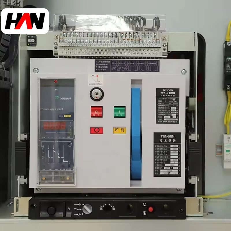
Description
24 kV Metal-Clad Switchgear
Armored, withdrawable distribution for 20 kV systems
Overview
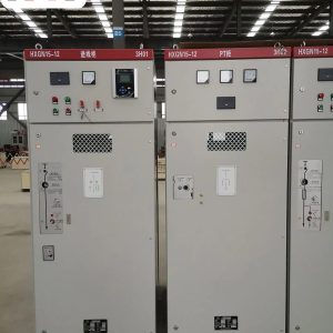
A 24 kV metal-clad switchgear assembly is the switchboard that distributes power on a 20 kV network. The 24 kV rating is the insulation level, not the operating voltage: it is what a 20 kV system needs to survive switching transients, lightning impulses and the occasional single-phase earth fault on an ungrounded or resistance-grounded network. In a smelting plant this voltage level appears where the incoming supply is 20 kV, and in export projects where the local grid is 20 kV or 22 kV rather than the 10 kV or 6 kV common in some domestic plants.
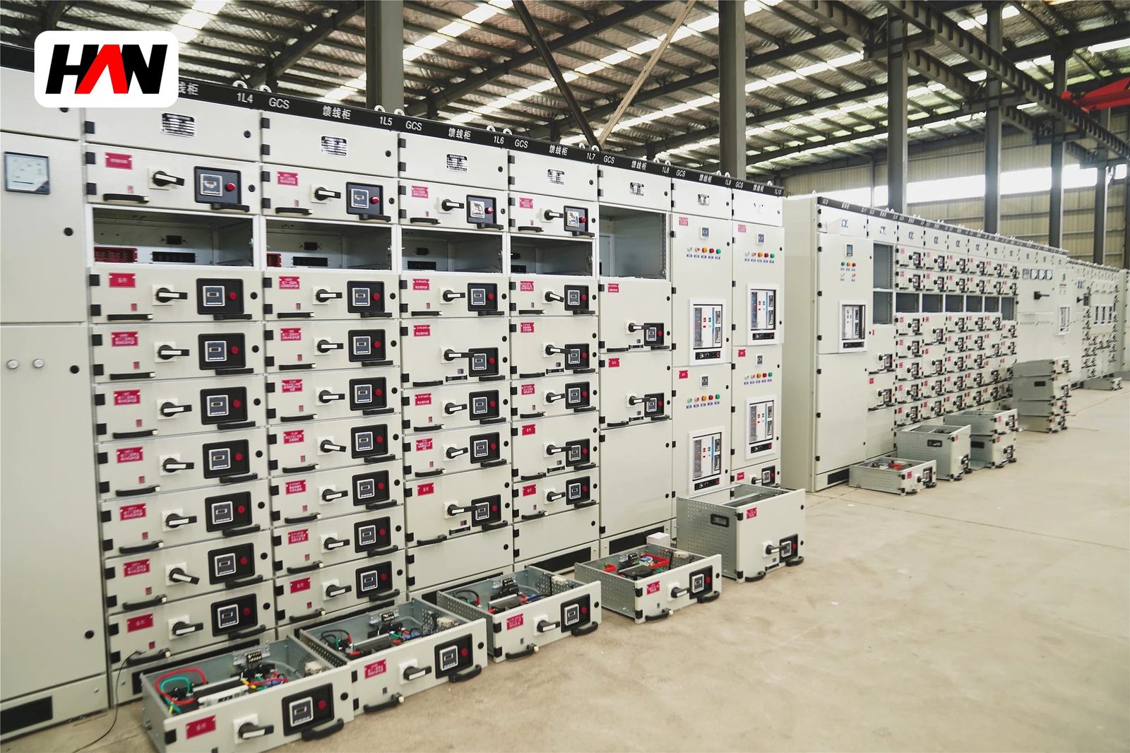
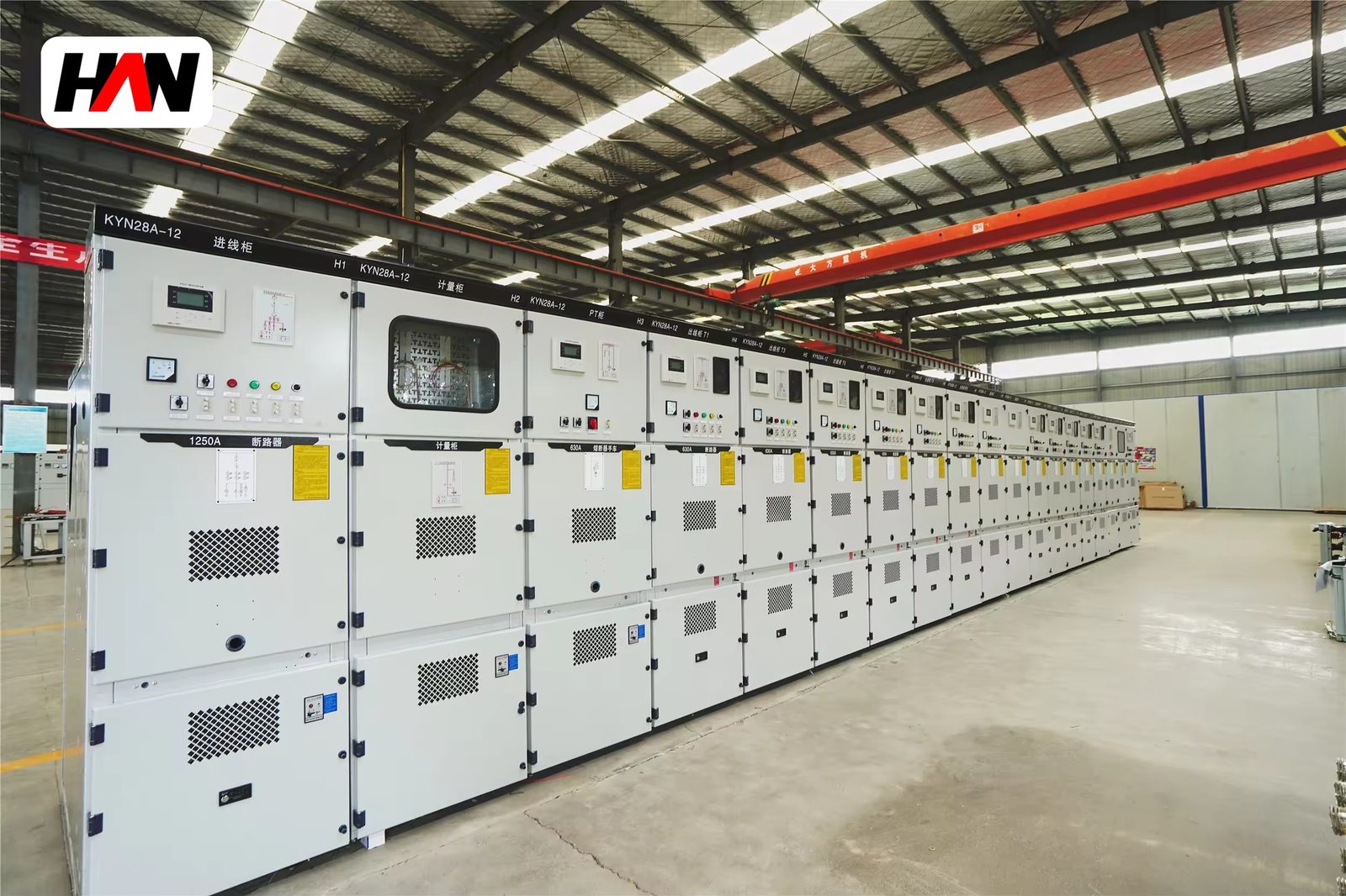
The assembly is metal-clad: every functional unit is a compartment of its own, separated from its neighbours by earthed metal partitions, with the circuit breaker on a withdrawable truck. HANI Metallurgy builds this family with a busbar rated from 630 A to 2500 A, a short-time withstand of 20 to 31.5 kA for 4 s and a lightning impulse level of 125 kV, to IEC 62271-200. The cubicles are used for incoming feeders, busbar sections and transformer feeders serving furnace transformers, distribution transformers and large motors in the melt shop and the auxiliary areas.
Technical Parameters
| Parameter | Unit | 630 A | 1250 A | 2500 A |
|---|---|---|---|---|
| Rated current | A | 630 | 1250 | 2500 |
| Rated voltage | kV | 24 | 24 | 24 |
| Short-time withstand, 4 s | kA | 20 | 25 | 31.5 |
| Peak withstand | kA | 50 | 63 | 80 |
| Lightning impulse withstand | kV | 125 | 125 | 125 |
| Power-frequency withstand, 1 min | kV | 65 | 65 | 65 |
| Protection degree, enclosure | — | IP4X | ||
| Service continuity | — | LSC2B, metal-clad, five compartments | ||
| Main busbar | A | 630 – 2500, copper, heat-shrink insulated joints | ||
| Design standard | — | IEC 62271-200 | ||
Typical values for reference. Final ratings, fault level and compartment dimensions are confirmed on the nameplate and the approved project datasheet.
How It Works Under Furnace Duty
The cubicle is divided into five compartments: main busbar, busbar riser, withdrawable breaker, cable and low-voltage instrumentation. The partitions are earthed steel, and each of the three power compartments has its own pressure relief flap that opens away from the operating aisle. This is the difference between metal-clad and metal-enclosed construction, and it is what allows one feeder to be worked on while the rest of the section stays energised.
Going from 12 kV to 24 kV changes the geometry more than the current rating suggests. The clearances between phases and to earth roughly double, because the air gap must hold 125 kV impulse and 65 kV power frequency, and a busbar that was a single flat bar at 12 kV becomes a spaced three-phase arrangement with insulated supports. The cubicle width grows to keep those clearances while still leaving a cable compartment deep enough for the termination. A 240 mm² cable needs a bend radius in the order of fifteen times its diameter, and a cable compartment that ignores this forces the installer to bend the core sharply at the lug, which is where a termination fails two years later.
The other 24 kV issue is condensation. The larger air volume and the higher surface area of the insulation supports give moisture more places to settle, and a smelting plant electrical room is often humid because of cooling water, washing and the adjacent wet dedusting area. Anti-condensation heaters with a hygrostat are therefore standard on this family, wired from a dedicated circuit so that they stay live when the feeder is isolated. Where the installation is above 1000 m, the insulation level and the current rating are both corrected for altitude before the order is placed.
Engineering notes
1. Check the phase-to-phase clearance against the actual cable lug and not only against the busbar drawing; the lug is usually the widest part of the circuit.
2. Heaters run continuously in humid rooms, so their circuit must be independent of the breaker auxiliary supply.
3. Above 1000 m altitude, both the dielectric withstand and the current-carrying capacity need correction before the rating is confirmed.
Key Advantages
- Five-compartment construction: busbar, riser, breaker, cable and low-voltage sections are separated by earthed metal, so a fault in one does not propagate into the next.
- Insulation margin for a 20 kV network: 125 kV impulse and 65 kV power-frequency withstand leave room for switching transients and for the occasional earth fault on an ungrounded system.
- Cable space sized for real cables: the compartment depth and the support positions are laid out for large core sizes and their bend radius, which is where most site rework on 24 kV boards comes from.
- Condensation control built in: hygrostat-driven heaters and a dedicated heater circuit keep the insulation supports dry through shutdowns and humid seasons.
- Withdrawable breaker truck: the switching device is exchanged or inspected without touching the busbar, which matters when the same board also feeds the furnace auxiliaries.
Selection and Commissioning
- Confirm the system voltage. A 20 kV network is served by 24 kV equipment; a 22 kV network may need the same board, but the insulation coordination and the arresters are checked against the actual system highest voltage.
- Fix the fault level and the clearing time. The short-time withstand must cover the prospective current for the time the upstream protection takes to clear, and the peak value sizes the busbar supports.
- Draw the cable entry before the order. Bottom entry from a trench, top entry from a tray and rear entry all change the compartment layout and the bending space available.
- Plan the earthing. The earth bar is continuous through the lineup, bonded to the building earth at both ends, and sized for the fault current of the section.
- Check the room, not only the board. Aisle width, door opening and floor loading decide whether the cubicles can be moved into place after the walls are up.
- Commission with a pressure test and a primary injection. Power-frequency withstand on the cables, then current injection through the CTs to prove the ratio, the relay setting and the trip circuit as one chain.
Frequently Asked Questions
Q1: Can 24 kV and 12 kV cubicles be bolted together in one lineup?
A: Not directly. The two families have different heights, depths, busbar pitches and insulation clearances, so a joint would need a transition cubicle with its own busbar and its own compartment. Mixing them usually means two separate sections with a cable or a busduct between them.
Q2: Why specify 24 kV equipment for a 20 kV system?
A: Because the equipment is rated by its highest voltage for equipment, and the standard level above 20 kV is 24 kV. It provides the insulation margin for switching overvoltage, for earth faults on an ungrounded network and for slight supply voltage excursions.
Q3: Is a 125 kV impulse level sufficient?
A: It is the standard level for 24 kV equipment and it is sufficient when the incoming cables are protected by arresters at the entry point and the earthing system is properly bonded. It becomes insufficient in practice when a long overhead line feeds the board without arresters, so the line entry is where the protection is reviewed.
Q4: When must the anti-condensation heaters be installed?
A: On any board in a humid room, in a room that is cooled at night and warm by day, in a basement, or where the board stands idle for long periods. In a melt shop the practical default is to fit them, because the cost is small against the price of a flashover on a damp insulation support.
Specify the 20 kV Board With the Plant
Send the system voltage, the fault level, the feeder list and the cable sizes, and HANI Metallurgy will return a 24 kV metal-clad lineup with the compartments and clearances fixed.