Description
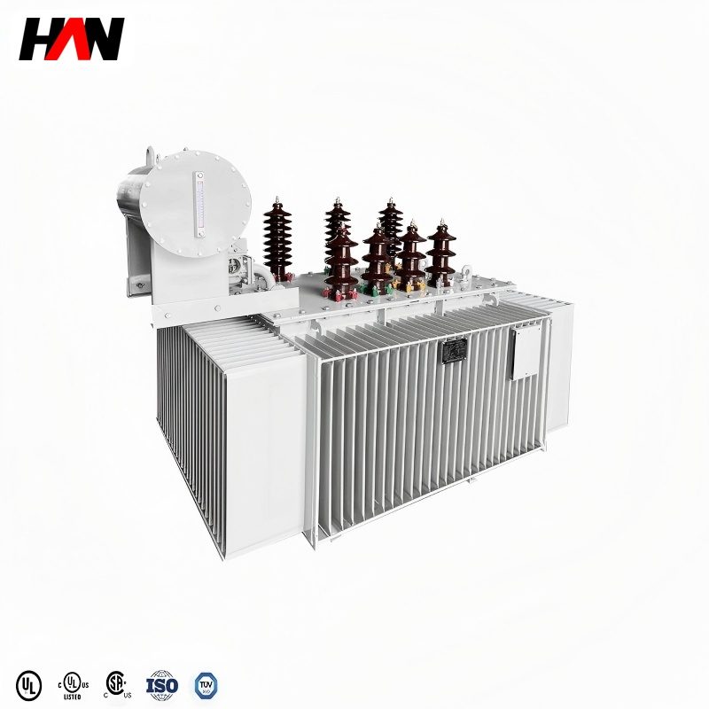
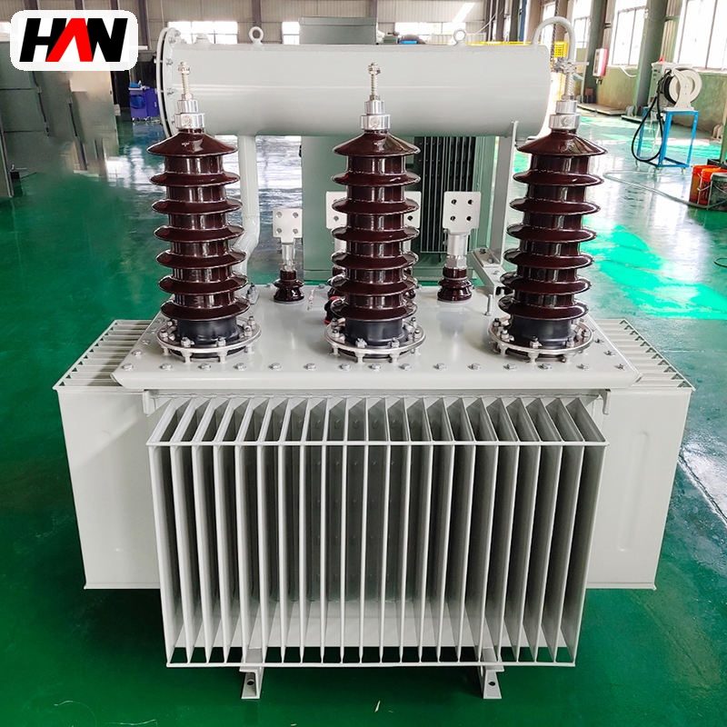
LF Ladle Furnace Transformer
Steady arc heating for ladle refining and alloy trimming
Overview
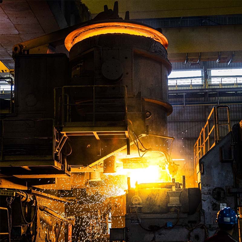
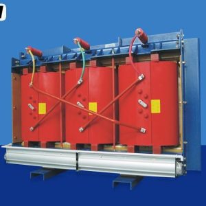
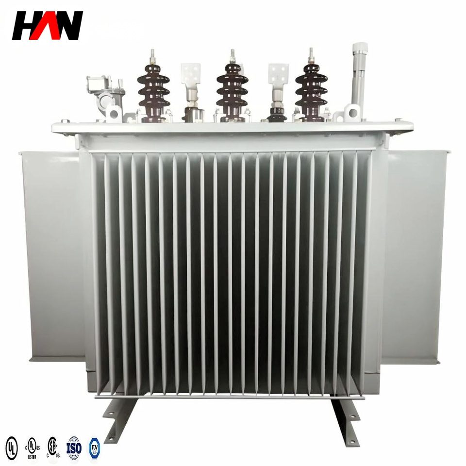
An LF ladle furnace transformer is the oil-immersed three-phase unit that steps the plant’s 35 kV distribution voltage down to the very low voltage and very high current that three graphite electrodes need to hold liquid steel at temperature inside a ladle. It sits downstream of the melting furnace, a short busduct run from the ladle car, on its own breaker. The secondary winding works between 180 V and 420 V and delivers 16 kA to 52 kA. Those numbers explain the design: the furnace does not melt scrap, it pushes current through a shallow slag layer, so low voltage is deliberate and high current unavoidable.
The unit covers 3 MVA to 20 MVA in a single family. Inside that range the duty is remarkably steady compared with an arc furnace: the arc is short, the current is regulated by electrode position and the load changes gently as the steel is trimmed. That stability is why a ladle furnace can do four jobs in one station: reheat steel that cooled during tapping, add ferroalloys and trim chemistry, give the slag time to absorb sulphur, and homogenise temperature before casting. HANI Metallurgy supplies these units with a complete ladle refining furnace, the rating, tap schedule and protection settings agreed against the ladle size and treatment route rather than a catalogue number.
Technical Parameters
| Parameter | Unit | 5 MVA | 10 MVA | 20 MVA |
|---|---|---|---|---|
| Rated capacity | MVA | 5 | 10 | 20 |
| Primary voltage | kV | 35 | 35 | 35 |
| Secondary voltage range | V | 180 – 300 | 200 – 350 | 220 – 420 |
| Secondary current, lowest tap | kA | 16 | 29 | 52 |
| Impedance voltage | % | 6 – 8 | ||
| Tap changer | steps | 9, on-load | 11, on-load | 13, on-load |
| Vector group | — | Yd11 | ||
| Cooling | — | ONAN / ONAF | ONAF | OFAF |
| Efficiency at full load | % | ≥ 98.5 | ≥ 98.8 | ≥ 99.0 |
| Design standard | — | IEC 60076-1 / GB 1094.1 | ||
Typical values for reference. Final ratings, impedance and tap schedule are fixed on the nameplate and the approved project datasheet.
How It Works Under Furnace Duty
In a ladle furnace the electrode tip is buried in a layer of synthetic slag that floats on the steel. The current path runs from the electrode, through the slag, into the steel bath and back up through the other electrodes. Slag is a poor conductor compared with steel, so most of the electrical energy is released as heat inside that thin layer, which is exactly where the metallurgy happens. That is why the secondary voltage is kept below roughly 420 V. A long arc radiates heat to the roof and ladle rim; a short submerged arc puts the energy into the slag and keeps the lining cooler. Low voltage also means high current, and high current forces every detail of the secondary design.
The tap changer is the only thermal control that acts instantly. Electrode regulation holds the current at its setpoint, so the arc length, and the power delivered at that current, is fixed by the secondary voltage. With 9 to 13 on-load steps the window is covered in fine increments; a coarse schedule overshoots the aim temperature and forces the operator to wait for the steel to cool. Fewer steps are needed than on an arc furnace because the window is narrower, but each step must be small and proven under load.
Thermally the load is gentler in amplitude and harder in duration. A heat may spend a long time at a fraction of rated power while the steel is stirred and sampled, and the transformer sits in that band with oil still hot from the previous treatment. Losses do not fall away with power: no-load loss plus resistive loss at part current keeps heating core and windings, and the radiator bank must remove it across a small oil-to-tank difference, which means slow natural circulation. Cooling is therefore sized on the whole treatment cycle, not on the rated point alone.
Engineering notes
1. Tapping is done on the high-voltage winding, so the low-voltage leads stay short and the high current never passes through a tap selector.
2. The secondary current sets the busbar, the water-cooled cable and the electrode arm cross-section; a 20 MVA unit at 220 V is a 52 kA design, not a scaled-up distribution transformer.
3. Roof and ladle car position, argon flow and wire feeder status belong in the trip matrix: an arc struck with the roof raised is a fault, not an operating condition.
Key Advantages
- Fine voltage resolution on load: the tap schedule divides the 180–420 V window into small steps, so bath temperature is trimmed by changing voltage instead of by waiting, and treatment time is not lost to overshoot.
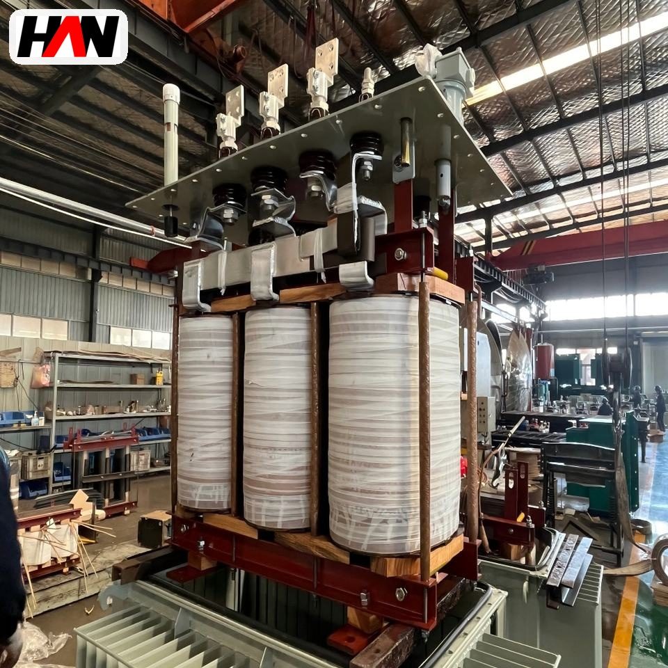
- Secondary built for tens of kiloamperes: parallel copper strips with transposed positions, short symmetrical leads, and a tank sized so the stray field of a 52 kA conductor cannot overheat the wall.
- Cooling matched to long holding periods: radiator area and fan staging are chosen for the low-power hour as well as the rated point, so the unit does not sit at its alarm threshold while steel is sampled.
- Protection shaped for a steady arc: with no bore-in surge to ride through, overcurrent and thermal settings follow the transformer’s own heating curve, which shortens fault clearance without nuisance trips.
- Interface for the ladle station: terminal box, cooling connections and interlock terminals are laid out for a melt shop floor, so roof, car and argon signals wire straight in.
Selection and Commissioning
- Start from the ladle, not the transformer. Ladle weight, the temperature lift after tapping and the holding time before casting give the electrical demand; the rating is set above it with margin for alloying heats.
- Fix the secondary voltage window from slag practice. A basic slag for deep desulphurisation favours the higher end; a thin slag under a tight rim favours the low end. It is a metallurgical decision with an electrical consequence.
- Choose impedance inside 6–8 %. Lower impedance gives a stiffer arc and easier current control at the same tap; higher impedance limits fault current. Agree the number with the electrode regulation supplier.
- Set the protection matrix. Overcurrent follows the thermal image; Buchholz, pressure relief, oil and winding temperature and tap position are wired as trip or alarm according to how the station is manned.
- Prove the interlocks before the first heat. Roof, ladle car, electrode clamp, argon and wire feeder signals are tested against the trip circuit with the breaker open, then again with the unit energised.
- Commission with three real heats. Oil and winding temperatures are logged from cold through three treatments. A curve still climbing after the third heat points to cooling, not to a setting.
Frequently Asked Questions
Q1: Can one transformer serve both the arc furnace and the ladle furnace?
A: Not in normal practice. The arc furnace needs a wide secondary window and a design for repeated short circuits; the ladle furnace needs a narrow, finely divided window and a steady arc. A shared unit would be oversized for one duty and over-stressed for the other.
Q2: Why is the secondary voltage only 180 V to 420 V?
A: Because the energy should be released in the slag, not in the arc column. A low voltage produces a short arc that stays buried in the slag layer, which improves heat transfer to the steel, protects the ladle lining and the roof, and gives the slag the temperature it needs for desulphurisation. The low voltage is achieved with a high current, which is why the secondary is built from parallel strips.
Q3: Does a long holding period overheat the transformer?
A: It can, if the cooling was sized only for the rated point. At low power the losses are smaller but the oil is still hot, natural circulation is slow, and the hot-spot can creep up over a long hold. The fix is design-side: radiator area and fan staging sized for part-load hours, plus a winding temperature alarm that reflects the hot-spot, not the oil top temperature alone.
Q4: How many ladle stations can one transformer feed?
A: One, as a rule. The secondary is a very high current circuit, and running it to a second station means long water-cooled cables, extra joints and low-voltage switching that few melt shops want. Where two stations exist, each gets its own transformer and feeder, and capacity is shared at the high-voltage bus.
Size the Transformer to the Ladle Station
Send the ladle capacity, treatment temperature and holding time, and HANI Metallurgy will return a rating, impedance and tap schedule.