Description
Isolation Transformer
Galvanic separation for electrode regulation and instrumentation
Overview
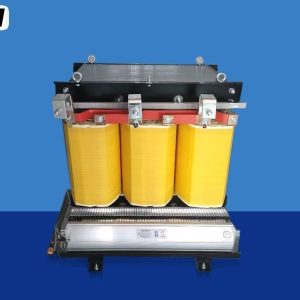
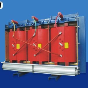
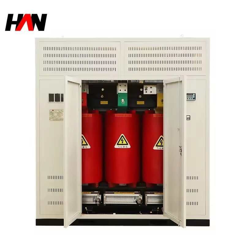
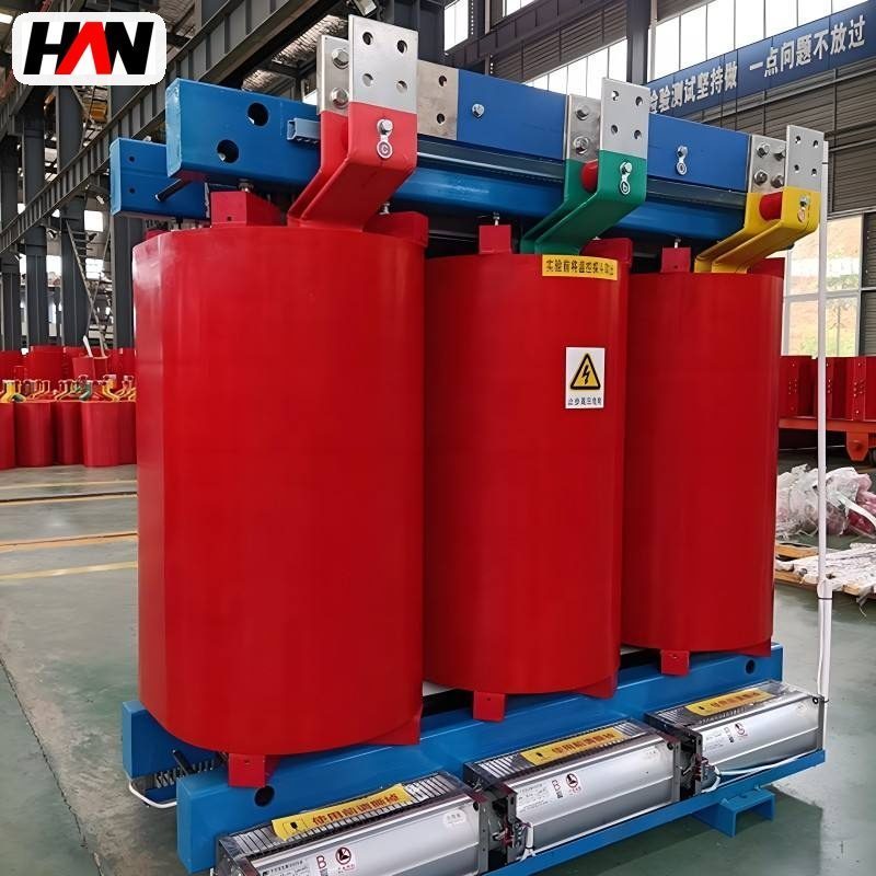
An isolation transformer for furnace control is a small dry-type transformer, typically between 1 kVA and 100 kVA, that puts a galvanic barrier between a control circuit and the power circuit it measures. In a melt shop the loads on that barrier are the electrode regulation system, the PLC rack, temperature and pressure transmitters, the analogue inputs that read arc current and arc voltage, and the control supply of the variable frequency drives on fans and pumps. All of them share one problem: they are referenced to a supply that carries the switching transients, harmonics and earth potential shifts of a furnace running at tens of thousands of amperes.
The unit is installed inside a control cabinet or in a small enclosure next to it. It takes 400 V from the local distribution board and delivers 230 V, or a 1:1 ratio where the same voltage is needed on a floating secondary. Because no conductor is common between primary and secondary, a fault on the power side cannot travel through the control supply, and a fault in the control circuit cannot escalate into the power system. For a furnace that is switched several times an hour, that separation is the cheapest reliability measure on the panel. HANI Metallurgy builds these units to IEC 61558-2-4 for control duty, with the core and winding practice of furnace transformers behind them.
Technical Parameters
| Parameter | Unit | 5 kVA | 25 kVA | 63 kVA |
|---|---|---|---|---|
| Rated capacity | kVA | 5 | 25 | 63 |
| Primary voltage | V | 400 | 400 | 400 |
| Secondary voltage | V | 230 | 230 | 400 |
| Impedance voltage | % | 4 – 6 | 4 – 6 | 4 – 6 |
| Vector group | — | Dyn11 | Dyn11 | Dyn11 |
| Electrostatic screen | — | fitted | fitted | fitted |
| Insulation class | — | F | F | F |
| Cooling | — | AN | AN | AN |
| Protection | — | IP00 | IP00 | IP23 |
| Efficiency at full load | % | ≥ 97.0 | ≥ 98.0 | ≥ 98.5 |
| Design standard | — | IEC 61558-2-4 / IEC 60076-11 | ||
Typical values for reference. Final capacity, ratio and protection degree are confirmed on the nameplate and the approved project datasheet.
How It Works Under Furnace Duty
Electrode regulation is the clearest case. The regulator decides whether to raise or lower an electrode by comparing the arc current with a setpoint, and it does that thousands of times per heat. The measurement is taken at the secondary side of the furnace transformer, where the current is huge and the voltage is a few hundred volts, and it is carried back to a controller running on 230 V control supply. Without isolation, the controller earth and the furnace power earth are the same node, so every arc strike and every electrode short lifts that node by tens of volts for a few milliseconds. The regulator then sees a phantom current step and moves the electrode when nothing has changed. A transformer with a floating secondary breaks that path.
The second mechanism is capacitive. Two windings wound one over the other form a capacitor, and high-frequency noise from the power winding crosses that capacitor into the control winding. An earthed electrostatic screen, a single turn of copper or aluminium foil placed between the windings and brought out to a terminal, intercepts that current and returns it to earth instead of letting it into the control circuit. The screen does not stop low-frequency disturbance, and it does not repair a bad earthing layout, but it removes the fast common-mode component that upsets analogue inputs and drive control boards.
The third mechanism is fault behaviour. With a separated secondary the first earth fault on the control circuit does not create a fault current; it simply shifts the reference, and the installation keeps running until the fault is found. That is the basis of an isolated system: no immediate trip, but an insulation monitoring device is then needed, because the second fault will trip two circuits at once. Because the impedance of a small transformer limits the secondary short-circuit current, protection is placed on the secondary side, with miniature circuit breakers sized to the control load rather than to the transformer inrush.
Engineering notes
1. The screen terminal must be earthed at the panel earth bar, not left floating and not shared with a signal reference.
2. Size for the connected load plus the inrush of the largest 24 V supply, not for the sum of the nameplate ratings.
3. An isolation transformer removes common-mode noise; it does not hold the load through a supply dip. That is the job of the UPS.
Key Advantages
- Galvanic separation for sensitive loops: the control circuit keeps its own reference, so arc transients and earth potential rise at the furnace no longer appear as measurement error.
- Electrostatic screen as standard: the foil between windings shunts capacitive common-mode current to earth, which is what protects analogue inputs and drive control boards in practice.
- Predictable fault current: the impedance of the unit limits secondary fault current to a level a miniature breaker can clear, so a wiring error inside the panel does not escalate.
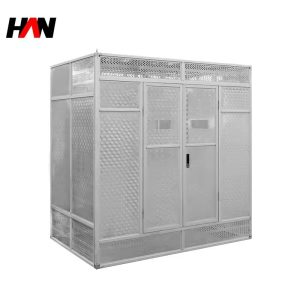
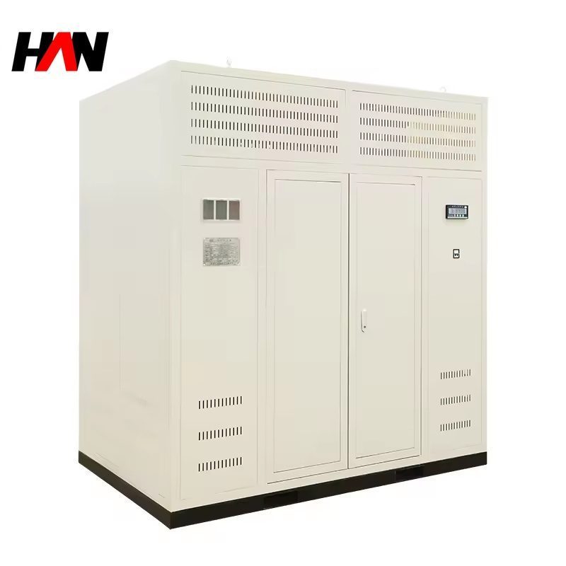
- Cabinet-friendly construction: a compact dry-type unit with terminal covers and an IP00 or IP23 finish that fits a 600 mm panel depth without a separate room.
- Built on furnace transformer practice: vacuum-impregnated windings, Class F insulation and the same quality control applied to the large furnace units, scaled to control duty.
Selection and Commissioning
- List the loads before the kVA. Add the continuous control load, the largest drive control supply and the start-up inrush, then round up; control supplies are often forgotten and later found to be the reason a 5 kVA unit runs warm.
- Choose the ratio honestly. Use a step-down unit where 230 V control is required and a 1:1 unit only where the same voltage must be kept on a floating secondary, for example feeding a drive control board that expects 400 V.
- Always take the screen. The cost is small and the benefit appears the first time an analogue channel starts drifting; without it, the transformer is doing only half of its job.
- Decide the earthing scheme. A floating secondary needs an insulation monitoring device and a documented first-fault alarm; an earthed secondary needs a clear single point and no parallel earth path through cable screens.
- Coordinate with the UPS. Put the isolated control supply downstream of the UPS where the load must ride through a dip, and keep the transformer upstream where it only has to filter noise.
- Commission with a disturbance record. Log the control supply and one analogue channel through several arcs; if the noise floor drops after the transformer is energised, the screen and the earthing are correct.
Frequently Asked Questions
Q1: Why does electrode regulation need an isolation transformer?
A: The regulator measures a small signal on top of a very large current, and it must do so while the arc is being struck and broken. Isolation keeps the controller reference away from the furnace power earth, so the transient that accompanies each strike does not reach the measurement input as a false step.
Q2: Can it replace a UPS?
A: No. An isolation transformer separates references and filters common-mode noise, but it has no stored energy, so its output collapses with the input. Where the PLC or the regulator must survive a supply dip, the isolated supply is placed downstream of the UPS, not instead of it.
Q3: What is the point of a 1:1 ratio?
A: The ratio is unchanged but the circuit is separated, so a 400 V control board can be fed from a floating source with no metallic connection to the plant earth. It is used where the load requires the same voltage but must not share a reference with the power system.
Q4: What capacity is needed?
A: The continuous control load plus the inrush of the largest supply module, with a margin for future cards. In practice a panel feeding a regulator, a PLC rack and a few transmitters lands between 5 kVA and 25 kVA; a 63 kVA unit is normally a drive control or distribution application.
Specify the Control Supply With the Furnace
Send the control load list, the required ratio and the panel layout, and HANI Metallurgy will return a capacity, a screening arrangement and a protection proposal.