Description
Loop-Feed Pad-Mounted Transformer
Ring-connected supply for plant and utility networks
Overview
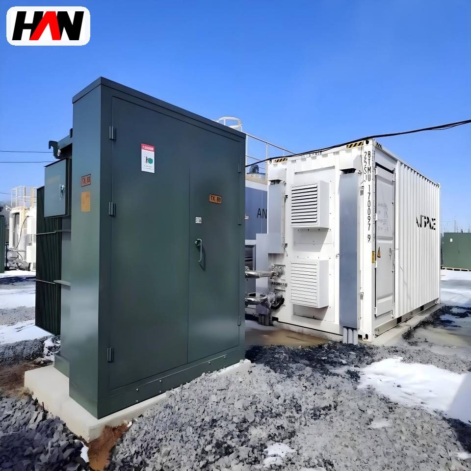
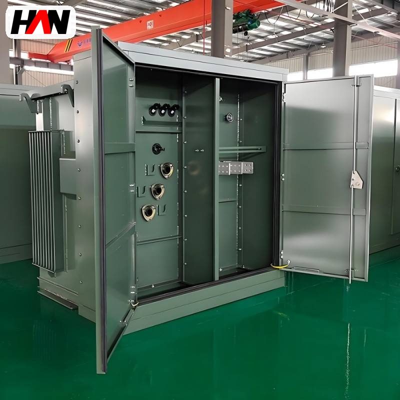
A loop-feed pad-mounted transformer is a ground-mounted distribution substation designed to be inserted into a ring rather than hung on the end of a radial feeder. It carries two high-voltage cable ways in and two out, with a switch on each, so the ring can be opened at the unit to isolate a faulted section while every other transformer on the loop stays energised. The transformer itself steps 34.5 kV down to 480 V or 400 V, and the whole assembly – switches, fuses, arresters, transformer and low-voltage compartment – is contained in a single locked enclosure standing on a concrete pad, normally at the edge of a yard or a road.
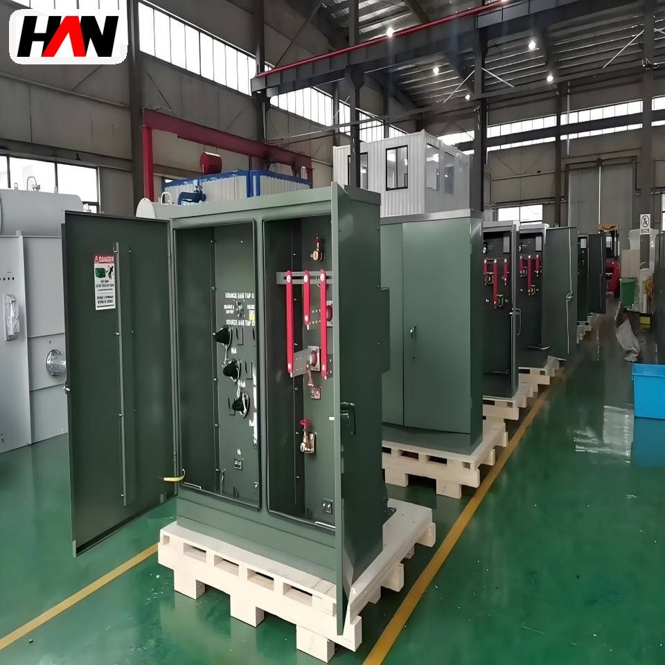
The construction follows the North American pad-mounted convention: separable insulated connectors on the high-voltage side, parking stands for the cable elbows, an arrester compartment, and a low-voltage compartment with the main breaker and the outgoing ways. That is a different maintenance culture from the European prefabricated substation, and the difference matters for an export project, because a utility crew expects to find the equipment it is trained on. Ratings run from 1000 kVA to 3000 kVA with a 65 K temperature rise, which is the usual specification where the ambient is high and the load is a plant auxiliary board rather than a single customer. HANI Metallurgy builds these units to IEEE C57.12.34 and IEC 60076-1. The melting feed itself is a different duty, handled by a dedicated EAF transformer.
Technical Parameters
| Parameter | Unit | 1000 kVA | 2000 kVA | 3000 kVA |
|---|---|---|---|---|
| Rated capacity | kVA | 1000 | 2000 | 3000 |
| Primary voltage | kV | 34.5 | 34.5 | 34.5 |
| Secondary voltage | V | 480 | 480 | 400 |
| Impedance voltage | % | 5.75 | 5.75 | 5.75 |
| Temperature rise | K | 65 | 65 | 65 |
| Cooling | — | ONAN | ONAN | ONAN |
| Loop configuration | — | two in, two out, with parking stands | ||
| HV terminations | — | separable insulated connectors, 200 A ways | ||
| Enclosure | — | pad-mounted, locked, dead-front | ||
| Efficiency at full load | % | ≥ 99.0 | ||
| Design standard | — | IEEE C57.12.34 / IEC 60076-1 | ||
Typical values for reference. Final ratings, impedance, way configuration and outline dimensions are confirmed on the nameplate and the approved project datasheet.
How It Works Under Furnace Duty
A ring works on the principle that every unit can be switched out of the loop without interrupting the loop. Each transformer has two ways in and two ways out, and the two loop switches are normally closed so that the cable forms a continuous path. If a cable section fails, the crew opens the two switches that bracket the faulted section, and every other transformer continues to be fed from the other side of the ring. The unit’s own transformer is protected separately by a fuse or a breaker behind the tee-off, and the loop itself carries only the current of the loads downstream, which is why the loop switches and the cable can be rated well below the sum of the transformer ratings.
The ANSI construction follows from that duty. High-voltage connections are made with separable insulated connectors, so a cable can be disconnected and parked on a stand inside the enclosure without a tool, and a faulted cable can be isolated in minutes. The enclosure is dead-front: all live parts are behind a barrier, and the only things the operator touches are the elbow connectors, the switch handles and the low-voltage breakers. Arresters sit in their own compartment so that a failed arrester does not contaminate the main cable compartment. This is why the ANSI unit looks different from a European prefabricated substation of the same rating: it is built around cable handling rather than around walk-in access.
The temperature rise value deserves a note, because 65 K does not mean the same thing in every standard. A 65 K rise is measured as the average winding rise over ambient, and it is paired with a permitted hot-spot allowance, so the insulation sees a higher temperature than the rise figure suggests. A 55 K unit of the same rating has more thermal margin and is heavier; a 65 K unit is smaller and cheaper but has less headroom for a hot yard or a sustained overload. Where the pad sits in direct sun next to a slag yard, the lower rise or a derated rating is the safer specification, and the ambient used for design must be the site ambient rather than a laboratory figure.
Engineering notes
1. Keep the ring open point documented and labelled; two open points on one ring is how a healthy loop becomes a set of radial feeders without anyone noticing.
2. Fit a fault indicator on the loop ways, or a faulted-circuit indicator, so the crew knows which section to isolate before opening the enclosure.
3. The separable connector needs the correct interface and lubricant; a mismatched elbow is a hot joint, not a minor deviation.
Key Advantages
- Two in, two out: a faulted cable section is isolated at the unit and the rest of the ring keeps running, so one cable failure does not stop the plant auxiliaries.
- Separable connectors with parking stands: cable work is done with the elbow, not with a spanner on a busbar, which shortens an outage and removes a common source of connection faults.
- Dead-front construction: the operator only handles insulated connectors and handles, so the enclosure can be opened safely in a yard without a switching programme for every inspection.
- Familiar to utility crews: built to the North American convention, so an export project or a plant with an IEEE-standard network is maintained with the practice the local team already uses.
- Compact on the ground: switchgear, transformer and low-voltage distribution share one pad, so the footprint in a congested yard is a few square metres rather than a building.
Selection and Commissioning
- Decide radial or loop first. A loop costs more cable and more ways per unit but removes single-cable outages; for dedusting or water treatment that must stay on, the loop is usually justified.
- Confirm the standard world. Choose the ANSI configuration where the network, the cables and the crews are North American practice, and a European prefabricated substation where walk-in access and IEC switchgear are the local norm.
- Match the secondary voltage to the existing boards. 480 V and 400 V are not interchangeable at the load end; fixing the low-voltage voltage fixes the motor and drive specification downstream.
- Set the rise for the site. 65 K is the common export specification, but in a hot, sun-exposed yard consider 55 K or a derated rating rather than relying on the overload allowance.
- Plan the cable and the pad together. Cable bending radius, entry position, spare ways and the parking stand location decide the pad size; a pad cast before the cable route is agreed is a change order.
- Commission with a field test. After installation, apply a DC insulation resistance test and a power-frequency withstand test on the high-voltage ways with the transformer disconnected, then check the loop switch interlocks and the fault indicators.
Frequently Asked Questions
Q1: Loop feed or radial – how is that decided?
A: By the cost of an outage. A radial unit is cheaper and simpler, and it is fine for a workshop board that can wait. Where a cable fault must not stop dedusting, water treatment or a critical fan, the loop pays for itself with the first fault.
Q2: Are ANSI and European pad-mounted units interchangeable?
A: Not directly. Cable terminations, protection practice, enclosure dimensions and access method all differ, and the local crew is trained on one of them. The electrical duty is similar, but installing the wrong convention creates a maintenance problem for the life of the unit.
Q3: What is the advantage of separable connectors?
A: They can be disconnected, tested and parked without tools or a cable termination, so a cable can be isolated and the loop restored in minutes. They also remove the bolted lug, which is where a large share of high-voltage connection failures begin.
Q4: How is a field withstand test done on site?
A: With the transformer disconnected and the cable removed or isolated, a DC insulation resistance test is followed by a power-frequency withstand test on the high-voltage ways. The test voltage and duration come from the standard the unit was built to and from the project specification, and the results are recorded against the factory values.
Ring-Feed the Loads That Cannot Stop
Send the ring layout, the cable sizes and the standard you build to, and HANI Metallurgy will return a loop-feed configuration with the ways, fusing and pad dimensions fixed.