Description
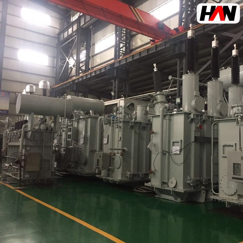
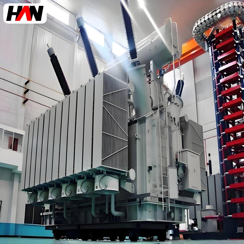
Submerged Arc Furnace Transformer
Continuous high-current supply for ore and ferroalloy smelting
Overview
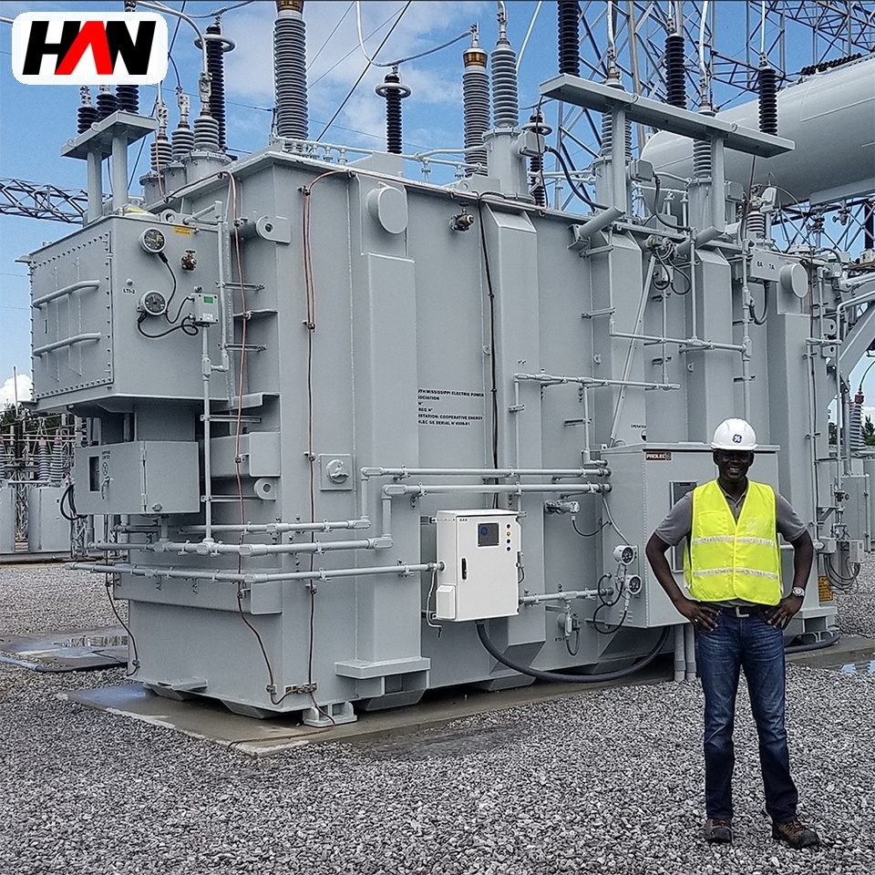
A submerged arc furnace transformer feeds the three electrodes of a closed or semi-closed smelting furnace in which the charge itself is part of the circuit. The electrode tip is buried in the burden, current passes through the ore and the coke bed to the hearth, and the furnace runs continuously for weeks. This is a different electrical animal from an arc furnace: the arc is short or absent, the resistance of the charge dominates, and the load is steady rather than cyclic. What the transformer has to deliver is a large, stable current at low voltage for a long time without interruption.
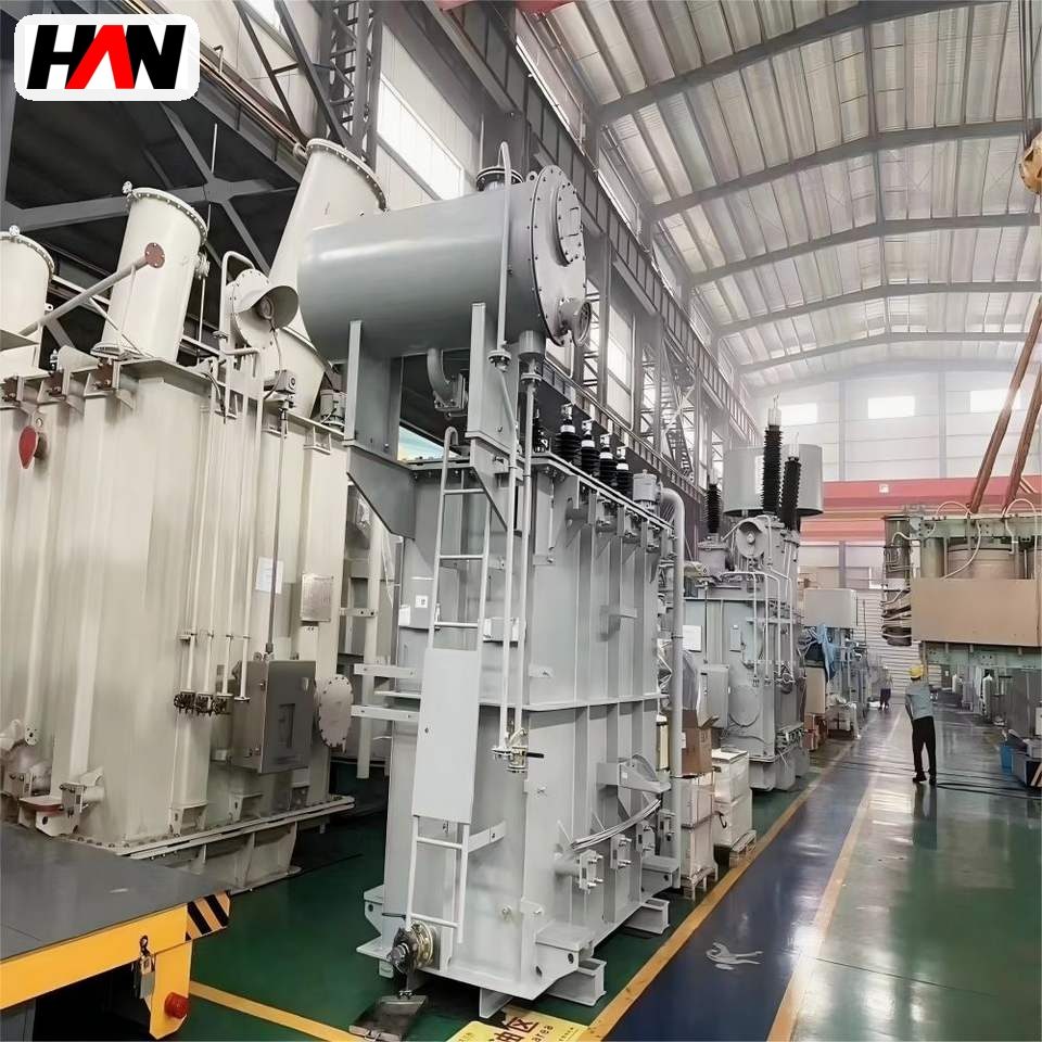
HANI Metallurgy builds these units from 3.5 MVA to 40 MVA, with 35 kV or 110 kV primaries and secondary voltages from 100 V to 400 V. Secondary current at the top of the range reaches 150 kA, which is why the low-voltage side is a fabricated copper-tube assembly rather than a cable. The family covers ferroalloy furnaces, silicon metal, calcium carbide and yellow phosphorus, and the same electrical logic applies to all of them: the transformer must match the resistance of the burden, and that resistance moves as the charge level and the charge composition change. A smelting submerged arc furnace and its transformer are therefore specified together, not separately.
Technical Parameters
| Parameter | Unit | 12.5 MVA | 25 MVA | 40 MVA |
|---|---|---|---|---|
| Rated capacity | MVA | 12.5 | 25 | 40 |
| Primary voltage | kV | 35 | 35 | 110 |
| Secondary voltage range | V | 130 – 250 | 140 – 300 | 150 – 400 |
| Secondary current, lowest tap | kA | 55 | 100 | 150 |
| Impedance voltage | % | 5 – 8 | ||
| Tap changer | steps | 21, on-load | 25, on-load | 27, on-load |
| Vector group / connection | — | 3-phase unit or bank of 3 single-phase units | ||
| Cooling | — | OFAF | OFAF | OFWF |
| Efficiency at full load | % | ≥ 98.8 | ≥ 99.1 | ≥ 99.3 |
| Design standard | — | IEC 60076-1 / GB 1094.1 | ||
Typical values for reference. Final ratings, impedance and tap schedule are fixed on the nameplate and the approved project datasheet.
How It Works Under Furnace Duty
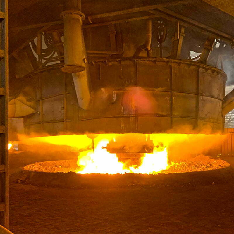
In a submerged arc furnace the electrode is pushed into the charge and a cavity of hot, partly molten material forms around the tip. Current leaves the electrode, crosses that cavity, and returns through the coke bed and the molten bath to the hearth electrode. The resistance of that path is much larger than the resistance of a steel bath in an arc furnace, so the furnace can absorb tens of megawatts at a few hundred volts without the current running away. Most of the heat is generated by resistive heating in the charge and only a fraction by the arc itself, which is why the process is quiet, continuous and thermally efficient compared with open-arc melting.
The consequence for the transformer is a low impedance, normally 5 % to 8 %. In an arc furnace a higher impedance is used to limit fault current and stabilise the arc; here the burden already provides the limiting resistance, and adding transformer impedance would only convert useful power into heat inside the windings. The second consequence is a large number of closely spaced taps, 21 to 27 in the sizes above. Burden resistance changes with charge height, particle size and coke ratio, and the operator needs to hold a target power by stepping voltage while electrode travel takes care of the fine regulation. A coarse tap schedule shows up immediately as electrode current imbalance and unstable furnace operation.
A smelting campaign has two electrical phases. During the early stage the furnace runs at constant capacity, with the transformer at its rating and the burden cold and resistive. Later, when the melt is established and the charge is being fed continuously, operation shifts towards constant current: the voltage tap is lowered and the current setpoint is held while the burden resistance falls. This is why the tap range is wide and why the low-voltage terminals, the water-cooled cables and the copper contact shoes on the electrode holders are all dimensioned for the highest current in the schedule, not for the average.
Engineering notes
1. Low impedance means a high prospective short-circuit current: bracing, busbar supports and the protection settings are calculated for that current, not for the rated one.
2. The secondary is a water-cooled copper tube run, so the transformer outline includes the terminal chamber, the pressure ring and the cooling water manifolds.
3. Impedance of the short net belongs in the same calculation as the transformer. Two percent of extra reactance in the busbar run can cost more power than the transformer’s own losses.
Key Advantages
- Built for continuous duty: cooling and thermal design follow a campaign that runs for weeks, so the rated point can be held without leaning on short-time overload allowances.
- Low impedance, on purpose: 5 % to 8 % keeps the voltage drop across the transformer small so that the power the furnace asks for actually reaches the burden.
- 21 to 27 on-load steps: fine increments let the operator hold power while the burden resistance drifts, and keep the three electrode currents within a narrow band.
- Secondary arranged for copper tube: terminal plates, phase spacing and enclosure are laid out for water-cooled tube and cable terminations at 55 kA to 150 kA.
- Available as a three-unit bank: above 15 MVA the same design can be supplied as three single-phase units, which eases transport, spares and phase-wise regulation.
Selection and Commissioning
- Start from the furnace power and the burden. Furnace shell diameter, electrode diameter and the target daily output fix the capacity; ore type and coke ratio decide how much of it can be delivered as current.
- Fix the secondary voltage window. The top tap must suit a cold, high-resistance burden; the bottom tap must suit the established melt. A window that is too narrow forces the electrodes to travel constantly.
- Decide three-phase unit or bank early. Transport limits, spare philosophy and whether phase-wise tap adjustment is wanted decide the arrangement before the layout is drawn.
- Agree the short net with the transformer. Busbar run, phase spacing and compensation are designed together, because the total reactance is what the electrodes see.
- Set protection for the real fault level. With impedance at 5 %, instantaneous overcurrent is set above the maximum operating current but well below the prospective fault current, and the thermal image follows the transformer curve.
- Commission with a load test on charge. Tap-by-tap current balance, cooling water flow and temperature, and gas and oil protection are proven over the first days of smelting, not only at no-load.
Frequently Asked Questions
Q1: Why does a submerged arc furnace transformer need so many taps?
A: Because the burden resistance is not a constant. Charge height, particle size and coke ratio all change it, and the furnace has to be held at a target power while that happens. A dense tap schedule lets the operator step voltage in small increments; with a coarse one, every change disturbs the electrode currents and the furnace loses stability for a while.
Q2: When is a bank of three single-phase units better than one three-phase unit?
A: Above roughly 15 MVA, transport and lifting limits often decide it, and a bank also reduces the spare holding to one unit. A bank allows each phase to be tapped separately, which helps against electrode current imbalance. One three-phase unit is more compact, cheaper to install and simpler to protect.
Q3: Why is the secondary made of water-cooled copper tube?
A: At 55 kA to 150 kA a conventional cable would need an impractical number of parallel runs and would still drop voltage. Copper tube carries the current in a small cross-section, is stiff enough to be supported against electromagnetic force, and is cooled from inside so the conductor temperature stays within the insulation limit.
Q4: Does low impedance create an unsafe short-circuit current?
A: It raises the prospective current, and that is handled in design rather than avoided. Coil bracing, busbar supports and terminal clamps are calculated for the peak force, and the feeder protection is set to clear a fault at the electrode quickly. The furnaces that suffer from this are the ones where the short net was added after the transformer was chosen.
Match the Transformer to the Furnace Load
Send the furnace capacity, ore type and incoming voltage, and HANI Metallurgy will return a rating, an impedance and a tap schedule for your smelting line.