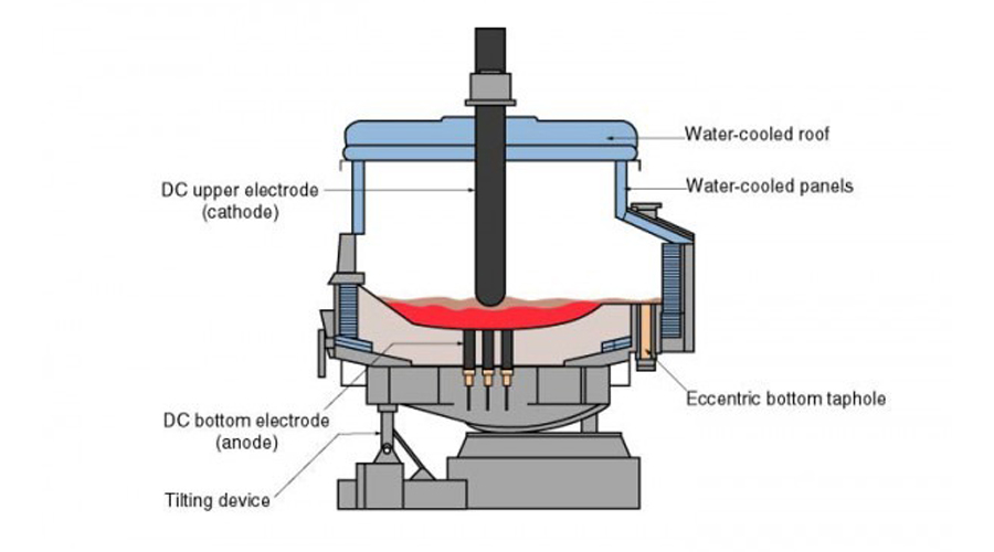
Submerged arc furnace diagram is an important step before the production of metal smelting equipment, which facilitates better and safer work. The purpose of this article is to explore the significance of submerged arc furnace diagrams and their role in the production of various materials through the submerged arc furnace process.
SAF are important equipment used in various industries such as metallurgy, steelmaking and chemical production. It operates through a unique process that involves melting the raw material beneath a layer of slag. To understand the functionality and operation of a SAF, a clear understanding of the submersible furnace diagram is necessary.
The Role of Submerged Arc Furnace Diagram
SAF diagrams provide a visual representation of the different components and their arrangement within the furnace. It usually includes labels for the furnace body, electrode, electrode lifting mechanism, charging system, tapping system and control system. This diagram helps engineers and operators understand the structure and function of the SAF.
a) One of the key components depicted in the submersible furnace diagram is the furnace body. This is where raw materials such as ore, flux and carbon are loaded and melted. The figure shows the shape and size of the furnace body, which can vary according to the specific requirements of the production process.
b) The figure also illustrates another key component of the submerged furnace – the electrode. The electrodes are responsible for delivering the current to initiate the arc and provide the necessary heat for the melting process. This figure shows the location and arrangement of the electrodes, as well as the electrode lifting mechanism that allows adjustment of the electrode position during operation.
c) Generally, the feeding system will also be shown in the drawings, which is responsible for introducing raw materials into the furnace. It may include a variety of equipment such as hoppers, conveyors and feeders, depending on the type and size of material being processed. The design drawing clearly shows how the supply system is integrated into the overall SAF structure.
d) Submerged arc furnace the tapping system shown in the diagram is used to extract the final product or slag from the furnace. It consists of tapping holes and channels as well as tapping equipment such as slag tanks or ladles. This diagram helps understand the location and arrangement of the tapping system, which is critical to safe and efficient operation.
e) Finally, the submersible furnace’s control system monitors and regulates various parameters such as temperature, current and feed rate. It provides an in-depth understanding of the control mechanism and its integration into the overall furnace setup.
In summary, submerged arc furnace diagram play a vital role in understanding the structure and operation of this important industrial equipment. It provides a visual representation of the different components and their arrangement within the SAF, allowing engineers and operators to understand the complex processes involved.
By understanding SAF diagrams, industry professionals can optimize SAF performance and efficiency, thereby improving material production and enhancing overall process control.

