Description
Induction Furnace Transformer
Isolation and voltage matching ahead of the medium-frequency supply
Overview
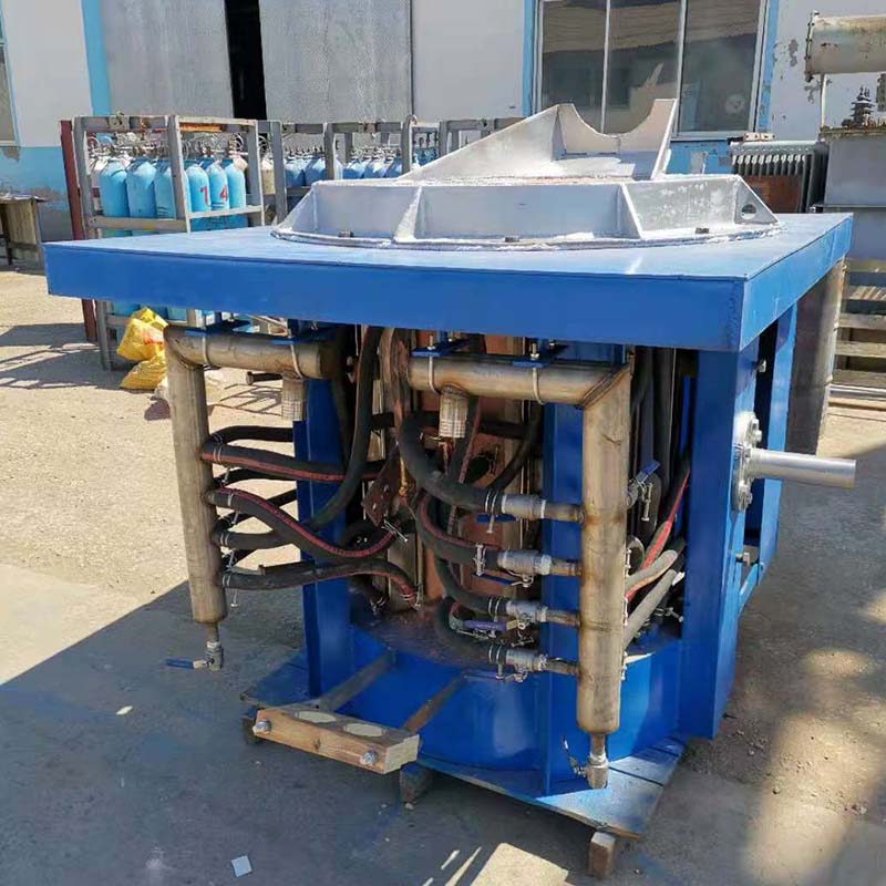
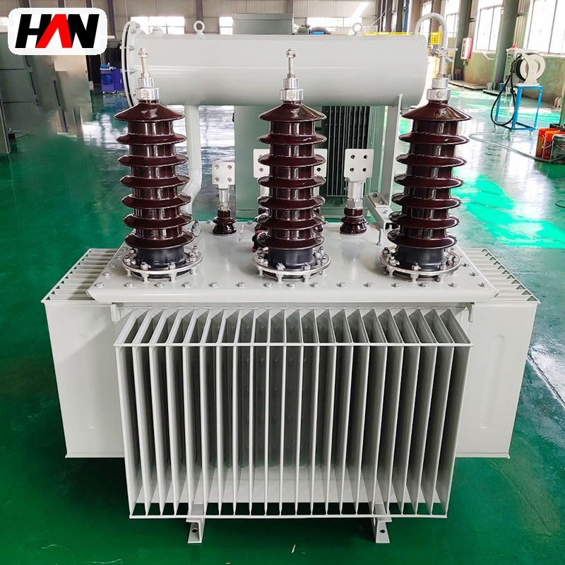
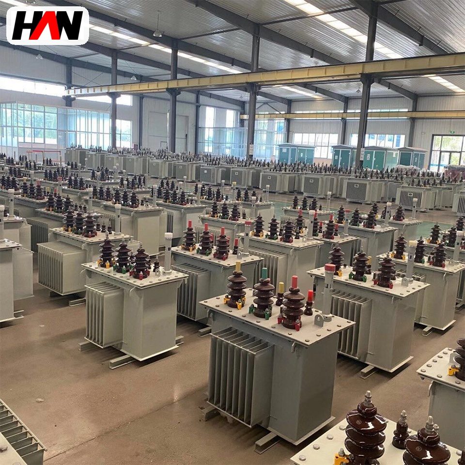
An induction furnace transformer is the unit that sits between the plant’s medium-voltage distribution and the medium-frequency power supply of an induction melting furnace. It does two jobs and neither of them is optional. It matches the 6 kV, 10 kV or 35 kV incoming voltage to a level the rectifier in the power supply can use, and it provides galvanic separation between the furnace circuit and the plant earthing system. The furnace itself is fed through a capacitor bank and a coil at a frequency far above the mains, and that whole conversion chain depends on a stable, isolated AC source in front of it.
The family covers 250 kVA to 3000 kVA, with secondary voltages from 400 V to 1000 V and a nominal impedance of 6 %. These are modest ratings compared with an arc furnace transformer, but the duty is not easier: the load swings through a melt cycle, the rectifier draws a non-sinusoidal current, and the transformer is usually installed close to the furnace where dust, heat and moisture are constant. HANI Metallurgy supplies these units for induction melting furnaces in foundries and steel plants, with the secondary voltage chosen against the power supply specification rather than against a standard list.
Technical Parameters
| Parameter | Unit | 500 kVA | 1500 kVA | 3000 kVA |
|---|---|---|---|---|
| Rated capacity | kVA | 500 | 1500 | 3000 |
| Primary voltage | kV | 10 | 10 | 35 |
| Secondary voltage range | V | 400 – 500 | 600 – 750 | 800 – 1000 |
| Impedance voltage | % | 6 | ||
| Tap range | — | ± 2 × 2.5 %, off-circuit or on-load | ||
| Vector group | — | Dyn11 | ||
| Cooling | — | ONAN | ONAF | ONAF |
| Efficiency at full load | % | ≥ 98.5 | ≥ 98.8 | ≥ 99.0 |
| Enclosure | — | Indoor open or enclosed, to project | ||
| Design standard | — | IEC 60076-1 / GB 1094.1 | ||
Typical values for reference. Final ratings, impedance and tap schedule are fixed on the nameplate and the approved project datasheet.
How It Works Under Furnace Duty
The furnace coil is not connected to the mains. The power supply rectifies the transformer secondary into a DC link, smooths it with a capacitor, and then switches it back into an AC current at a few hundred hertz for the coil. The secondary voltage therefore sets the DC link voltage, and the DC link voltage sets the maximum power the inverter can push into the coil. In a six-pulse rectifier the DC voltage is roughly 1.35 times the secondary line voltage, which is why an 800 V to 1000 V secondary is common on larger units: it keeps the DC link high enough to reach full power without drawing an unreasonable current.
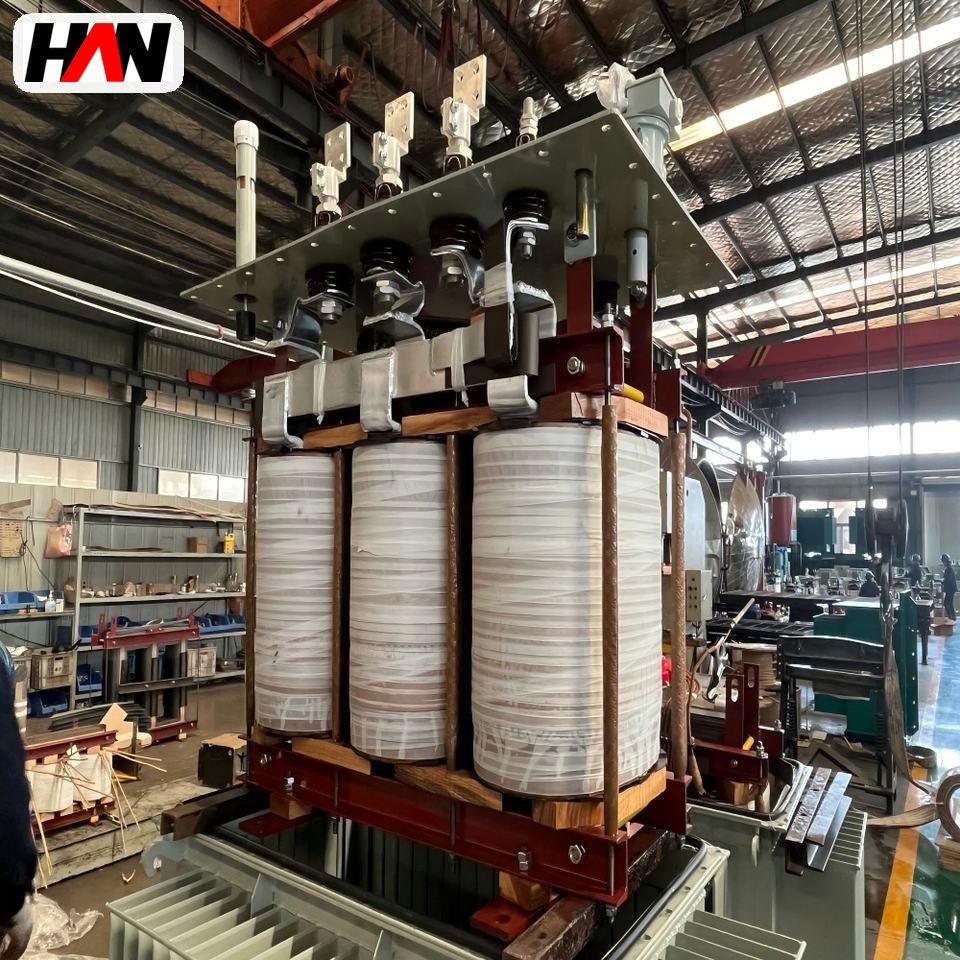
The rectifier is a non-linear load. Current is drawn in short pulses rather than in a sine wave, so the transformer carries harmonic currents that heat the windings and the core beyond what the fundamental current would suggest. That is the reason for choosing the winding conductor arrangement, the core flux density and the cooling with harmonic content in mind rather than by nameplate current alone. Where a compensating capacitor bank is installed on the same bus, the transformer and the bank have to be checked together, because a resonant point that falls near a harmonic the rectifier produces will amplify it.
The thermal cycle is short and repetitive. A melt shop charges cold scrap, runs at high power to melt down, holds for alloying and superheat, then pours; the transformer follows that curve for every heat, several times a shift. Losses and temperatures rise and fall with it, and the unit is asked to hold its insulation life through thousands of such cycles. A transformer specified only for continuous rated load will look adequate on paper and will run hotter in practice, because the load peaks come with a power factor and a harmonic spectrum that were not in the rated condition.
Engineering notes
1. The secondary voltage is chosen from the power supply’s DC link requirement, not from the furnace coil voltage; the matching transformer for the coil is inside the power supply.
2. A Dyn11 vector group gives a low-impedance path for triplen harmonics and keeps the secondary neutral available for the control and auxiliary circuits.
3. Dust and moisture decide the enclosure: an enclosed unit in a foundry needs a filtered air path and scheduled cleaning, or the cooling ducts will block within a season.
Key Advantages
- Clean isolation for the furnace circuit: the power supply, the coil and the capacitor bank work on a separated system, so a fault in the furnace does not put the plant earth system at risk.
- Voltage matched to the DC link: secondary taps at ± 2 × 2.5 % let the unit be set to the actual incoming voltage on site instead of relying on the nominal figure.
- Thermal design for cyclic load: windings and cooling are dimensioned for the melt-hold-pour rhythm, with harmonic heating included in the calculation.
- Compact footprint for the melt deck: the unit is laid out to sit beside the power supply, with cable entry and cooling arranged for a congested furnace platform.
- Enclosure for the real room: from an open indoor unit to a weatherproof tank for outdoor siting, chosen against the dust and water conditions of the actual installation.
Selection and Commissioning
- Start from the power supply, not the furnace. The rectifier input voltage and current, the DC link range and the inverter rating define the transformer; ask the power supply supplier for those three numbers first.
- Add margin for harmonic heating. A unit sized exactly at the fundamental kVA runs hot on a six-pulse rectifier; the allowance is agreed with the supplier and written into the specification.
- Check the compensation scheme. Capacitor steps, detuning reactors and the transformer impedance form one circuit, and the harmonic study has to include all three.
- Choose the enclosure for the room. Indoor melt deck, basement or outdoor yard each imply a different IP rating, a different air path and a different maintenance interval.
- Wire the protection into the power supply interlock. Winding temperature, oil temperature and fan failure should stop or derate the inverter, not only raise an alarm in the electrical room.
- Commission on a real melt. Log temperatures through several complete cycles, confirm the tap position against the measured incoming voltage and record the harmonic current spectrum at the secondary.
Frequently Asked Questions
Q1: Why does an induction furnace need a dedicated transformer?
A: Because the power supply needs a specific input voltage, a separated earth reference and a source that can absorb cyclic and harmonic loading. A general-purpose distribution transformer on the same bus would be shared with other loads, would see voltage dips from them, and would not be sized for the harmonic content the rectifier produces.
Q2: Can the furnace be connected directly to the low-voltage workshop network?
A: For small units it is sometimes done, but the furnace then shares its supply with welding sets, cranes and drives, and every voltage dip shows up in the melt. Above a few hundred kVA the supply is taken from medium voltage through a dedicated transformer, which also keeps the high currents of the power supply in a short, controlled path.
Q3: How is the transformer capacity matched to the power supply rating?
A: The rated kVA is set from the rectifier input current and voltage at the lowest tap likely to be used, then increased for harmonic heating and for the power factor the rectifier presents. The nameplate kVA alone is not enough: two supplies of the same kW can load the transformer differently depending on their rectifier design.
Q4: What do harmonic currents do to the transformer?
A: They add eddy-current and stray losses in the windings, the clamps and the tank, so the unit runs hotter than the fundamental current suggests. They also circulate in the delta winding and load the neutral if one is brought out. The practical answer is a design with harmonic loss allowance and a temperature supervision that reflects the hot-spot.
Match the Transformer to the Power Supply
Send the inverter rating, the rectifier input voltage and the incoming supply, and HANI Metallurgy will return a rating, an impedance and a tap setting for your furnace.