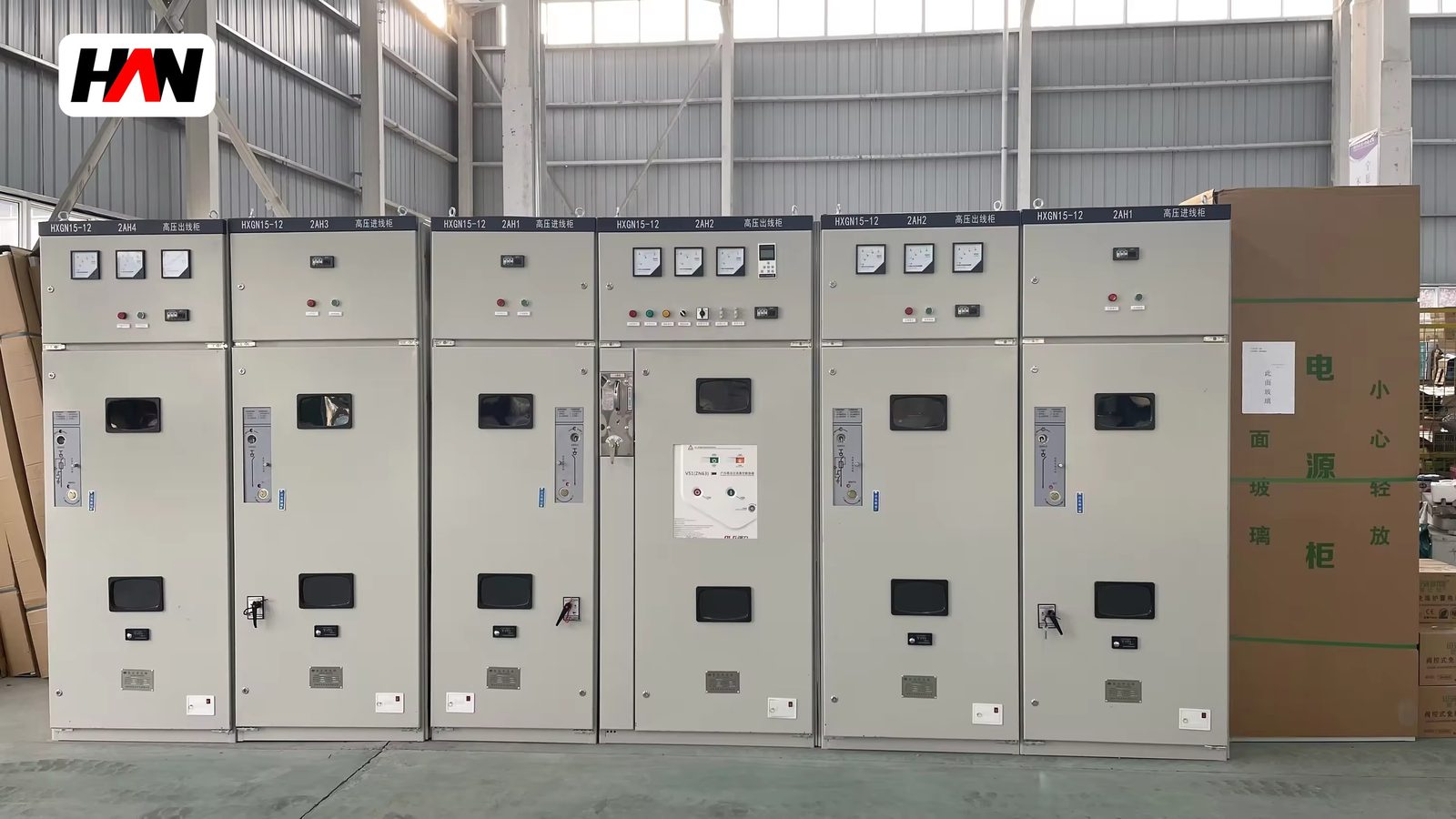
Description
Furnace Transformer Feeder Switchgear
Frequent switching and fault clearance at the furnace feeder
Overview
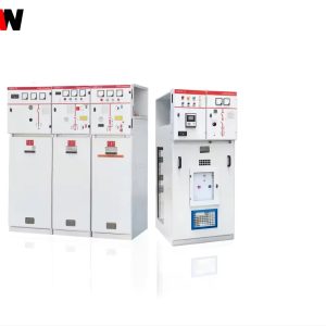
A furnace transformer feeder switchgear is the 12 kV cubicle that connects the plant busbar to the primary winding of a furnace transformer. It is a short electrical distance and a long duty list. The breaker in this cubicle is switched several times per heat, it clears the fault current when a transformer, a cable or a short net fails, and it is the point where the transformer protection, the tap changer and the furnace control system meet. On a melt shop single line diagram this is normally the most operated circuit in the whole plant.
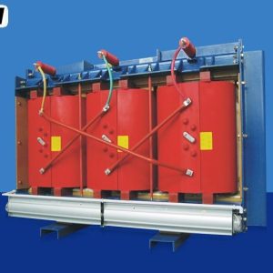
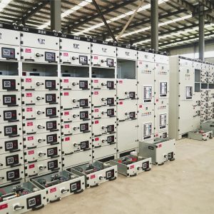
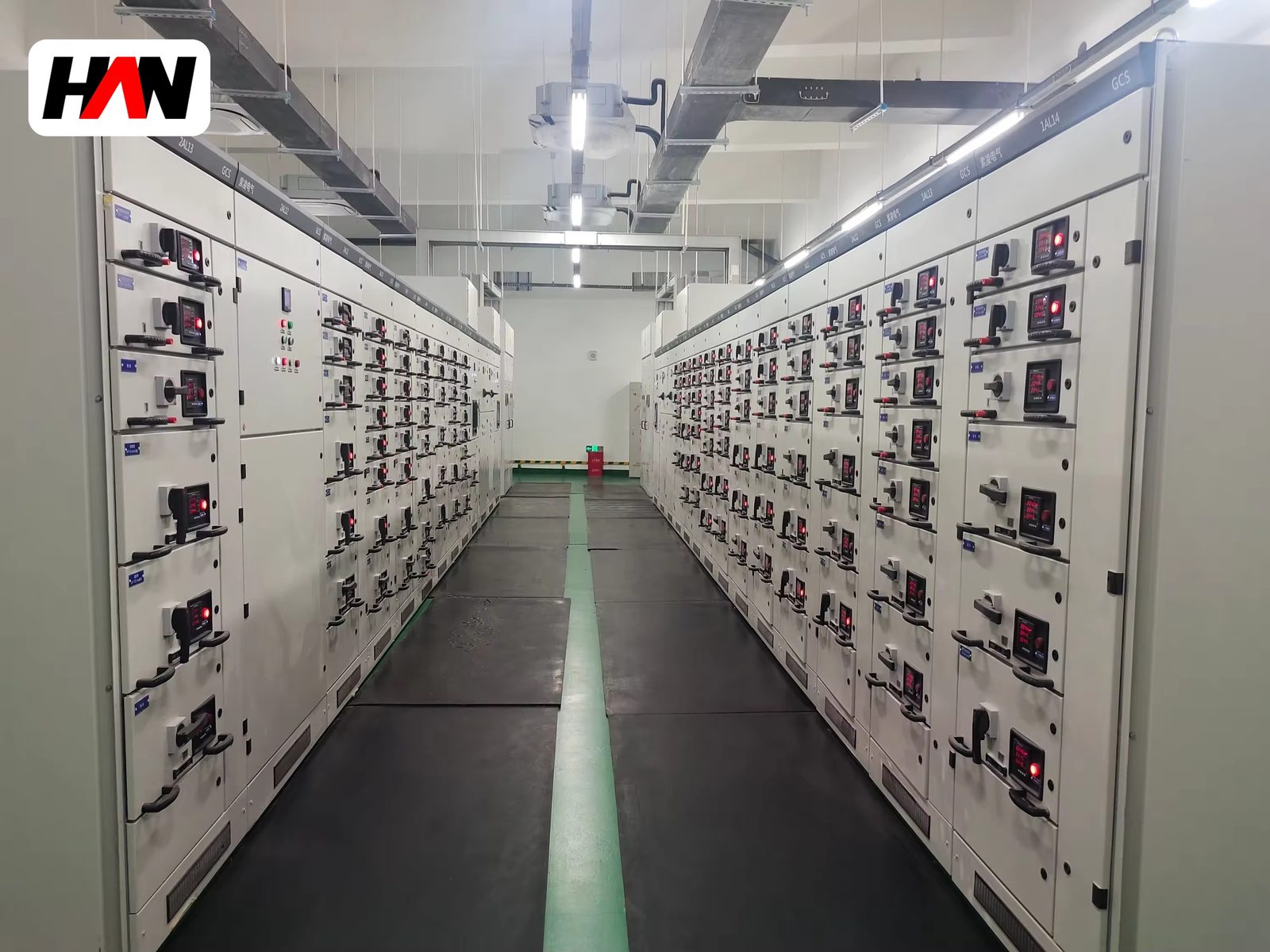
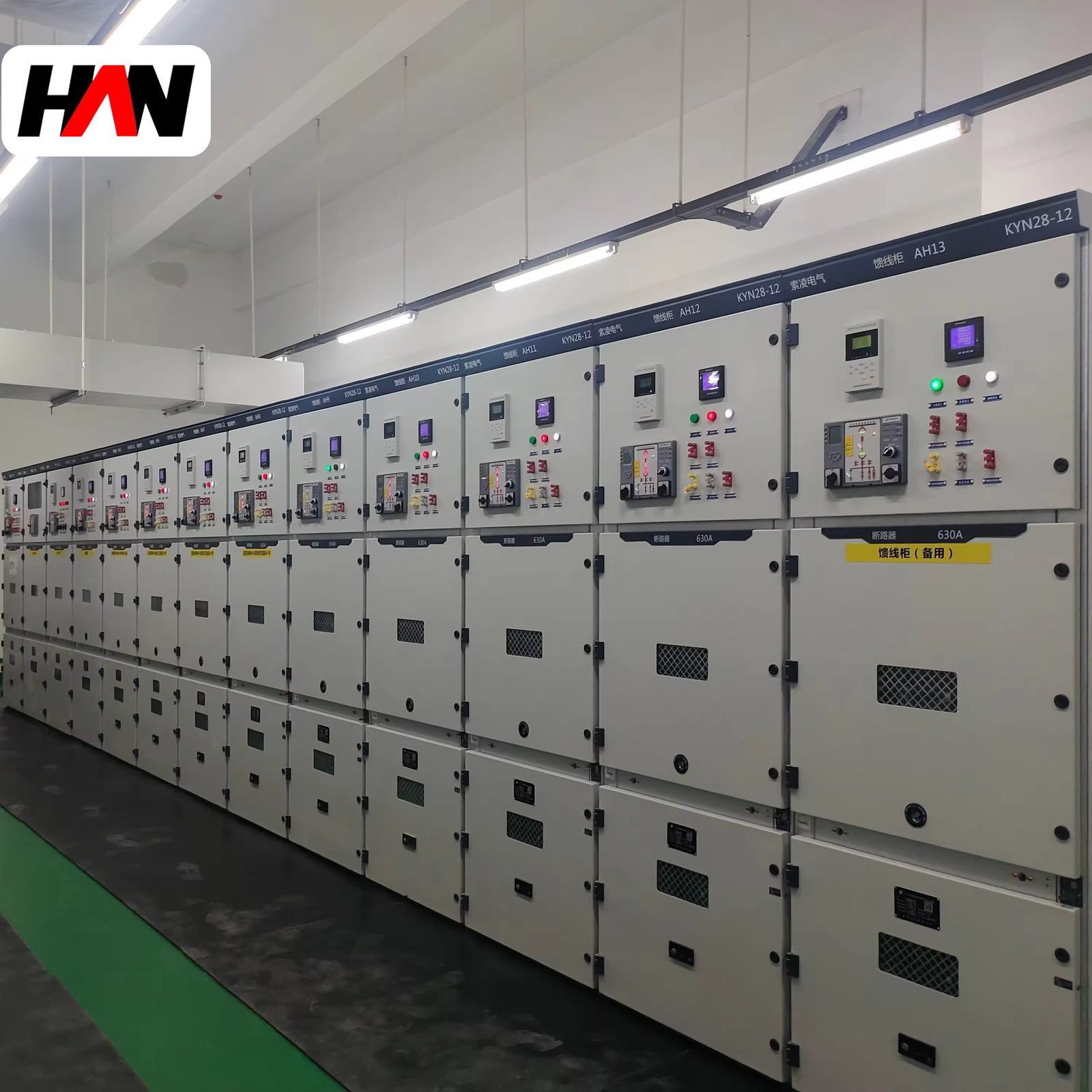
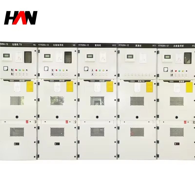
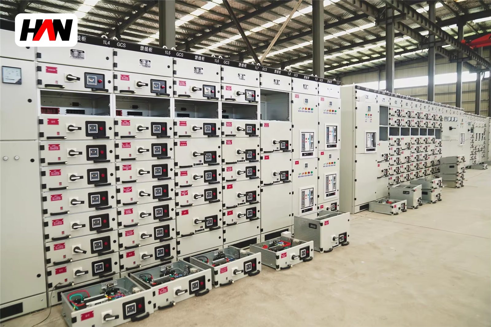
The unit is built on a withdrawable vacuum breaker in a metal-clad enclosure rated 12 kV, with a main busbar rated from 630 A to 3150 A and a short-time withstand of 20 to 40 kA for 4 s. Service continuity is LSC2B, which means each functional unit has its own breaker compartment, its own busbar compartment and its own cable compartment, and the breaker can be withdrawn and replaced while the busbar stays live. HANI Metallurgy builds these cubicles as the feeder half of a furnace power train, paired with an EAF transformer or a ladle furnace transformer and a short net, so that the protection settings, the cable size and the breaker rating are agreed as one package instead of three.
Technical Parameters
| Parameter | Unit | 630 A | 1250 A | 2000 A |
|---|---|---|---|---|
| Rated current | A | 630 | 1250 | 2000 |
| Rated voltage | kV | 12 | 12 | 12 |
| Short-time withstand, 4 s | kA | 25 | 31.5 | 40 |
| Peak withstand | kA | 63 | 80 | 100 |
| Lightning impulse withstand | kV | 75 | 75 | 75 |
| Main busbar rating | A | 630 – 3150, copper, silver-plated joints | ||
| Circuit breaker | — | vacuum, withdrawable truck, spring-charged | ||
| Protection scheme | — | three-stage overcurrent + zero sequence, transformer differential optional | ||
| Mechanical endurance | operations | 30 000 | ||
| Service continuity | — | LSC2B, metal-clad | ||
| Design standard | — | IEC 62271-200 / IEC 62271-100 | ||
Typical values for reference. Final ratings, fault level and protection settings are confirmed on the nameplate and the approved project datasheet.
How It Works Under Furnace Duty
The cubicle is divided into four compartments by earthed metal partitions: the main busbar compartment at the top, the withdrawable breaker compartment in the middle, the cable compartment at the bottom rear, and a low-voltage compartment on the front for relays, meters and terminals. Each compartment has its own pressure relief flap, so an internal arc is vented upwards or backwards instead of through the front panel where an operator may be standing. The segregation is what LSC2B buys: a fault in one cable compartment does not take the busbar out of service, and a breaker can be exchanged without isolating the section.
Five mechanical interlocks govern the operating sequence. The breaker cannot be closed unless the truck is in the service or the test position and the earthing switch is open. The truck cannot be moved from service to test while the breaker is closed. The earthing switch cannot be closed while the truck is in the service position. The cable compartment door cannot be opened unless the earthing switch is closed. And the truck cannot be pushed in from test to service while the earthing switch is closed. The keys and the shutters are mechanical, not software, so the sequence holds even when the control supply is dead.
Frequency is the real design driver. A furnace feeder may make tens of thousands of operations in a few years, far more than a normal distribution feeder, and every closing operation deposits a small amount of contact erosion and releases a burst of switching overvoltage into the transformer primary. That is why the breaker uses vacuum interrupters with a rated electrical endurance matched to the duty, why the transformer side is protected by surge arresters or an RC absorber, and why the breaker is on a withdrawable truck: when the interrupters reach the end of their life the truck is exchanged in a short stop instead of a busbar outage. Short-circuit withstand and temperature rise are checked together, because a busbar joint that runs hot loses contact pressure and then becomes the fault.
Engineering notes
1. The instantaneous overcurrent stage is set above the transformer inrush peak, otherwise every energization trips the feeder.
2. Buchholz, winding temperature and tap changer fault contacts are wired to trip the feeder, not only to alarm, on furnace transformers.
3. Silver-plated busbar joints and a torque check at commissioning are the cheapest defence against a hot joint over the next decade.
Key Advantages
- Built for the operation count: the vacuum breaker, the operating mechanism and the auxiliary contacts are selected for a feeder that switches several times per heat, not for a feeder that switches twice a year.
- LSC2B segregation: separate breaker, busbar and cable compartments with individual pressure relief, so a single cable fault does not shut down the whole 12 kV section.
- Mechanical five-point interlock: the operating sequence is enforced by keys and shutters that work without control power, which is exactly when mistakes are made.
- Protection matched to the transformer: three-stage overcurrent, zero sequence and optional differential are set against the transformer inrush and the short net impedance, not against generic feeder defaults.
- Serviceable in a short stop: the withdrawable truck and the front-accessible current transformers let a maintenance team replace the switching device between heats instead of waiting for a planned outage.
Selection and Commissioning
- Fix the fault level first. The transformer feeder must withstand the prospective short-circuit current at the busbar for the clearing time of the upstream protection, and the peak value decides the busbar bracing.
- Size the cable with the transformer, not after it. Cable cross-section, parallel runs and the length to the transformer primary decide both the voltage drop and the earth fault current the zero sequence stage will see.
- Set the protection in three stages. Instantaneous above inrush, a short time-delay stage for the transformer, and an inverse-time stage coordinated with the upstream incomer.
- Define the interface list. Trip and alarm from Buchholz, winding temperature, tap changer and cooling plant are listed with their contact type before the relay configuration is frozen.
- Test the interlocks mechanically. Every one of the five sequences is operated by hand at commissioning, with the control supply off, and the result is recorded.
- Do a primary injection test. Current is injected through the primary circuit to prove the current transformers, the relay settings and the trip circuit together, because a correct relay with a wrong CT ratio still trips at the wrong current.
Frequently Asked Questions
Q1: Why does a furnace feeder use a vacuum breaker rather than another interrupting medium?
A: Because of the operation count. A vacuum interrupter keeps its dielectric and its contact resistance over tens of thousands of operations with almost no maintenance, and it needs no gas monitoring or oil sampling. For a circuit that is switched several times per heat, that difference decides the maintenance workload of the whole substation.
Q2: How is switching overvoltage at the transformer controlled?
A: With surge arresters or an RC absorber on the transformer side of the breaker, close to the transformer terminals. Vacuum interrupters can produce steep-fronted switching transients when a small inductive current is interrupted, and the first turn of the primary winding is what absorbs them if no suppression is fitted.
Q3: Withdrawable or fixed breaker?
A: Withdrawable for a furnace feeder, because the breaker is the part that wears and because the truck gives a visible isolating gap for cable work. Fixed units are used where the feeder is rarely operated and the panel space is tight, but they turn a breaker replacement into a busbar outage.
Q4: Can the furnace feeder share a busbar section with a compensation or filtering plant?
A: Yes, provided the fault level of the section, the short-circuit rating of every cubicle and the protection coordination are recalculated with the filter or capacitor bank connected. The bank changes the fault current path and can hold a charge after the feeder is opened, so an earthing and discharge procedure is part of the design.
Match the Feeder to the Furnace
Send the transformer rating, the busbar fault level and the switching duty, and HANI Metallurgy will return a 12 kV feeder cubicle with the breaker, the CTs and the protection settings agreed together.