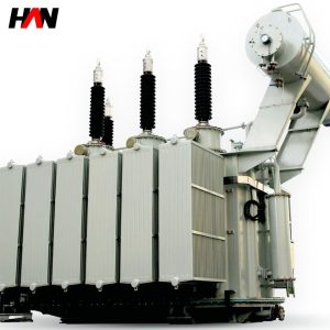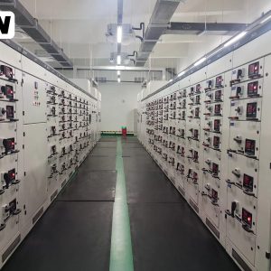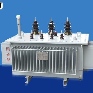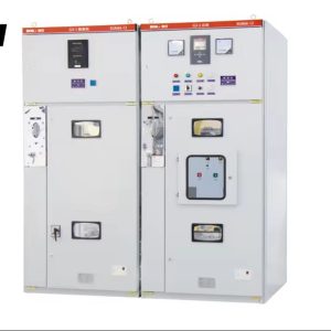
Description
Amorphous Dry-Type Transformer
Lower no-load loss for intermittent plant loads
Overview
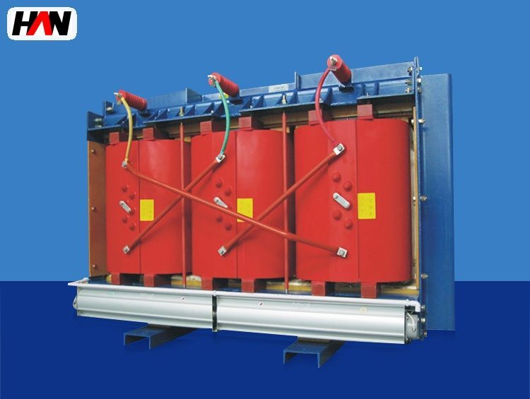
An amorphous dry-type transformer is a cast resin distribution transformer built on a core of amorphous alloy instead of grain-oriented silicon steel. The alloy is produced as a thin ribbon and wound into the core shape, and its atomic structure has no crystal lattice for the magnetic domains to align with, so the energy needed to magnetise and re-magnetise it is significantly lower than in a conventional core. In a steel plant that property is worth money wherever a transformer stays energised while carrying very little load: lighting boards, workshop sockets, maintenance supplies, water pumps, compressed air dryers and the small distribution units that feed a canteen or an office block.
The unit takes 10 kV or 20 kV from the plant network and delivers 400 V, in ratings from 50 kVA to 2500 kVA. It is air-cooled, oil-free and normally installed inside a workshop or a substation room, with the coils cast in epoxy resin for protection against dust and humidity. Because a large part of the loss in these ratings is no-load loss rather than load loss, the choice of core material changes the annual energy bill more than a change of conductor section would. That makes the type interesting for the auxiliary side of a melt shop, where the load factor is often low and the hours energised are long. The main furnace feed is a different duty, handled by the furnace transformer.
Technical Parameters
| Parameter | Unit | 315 kVA | 630 kVA | 1250 kVA |
|---|---|---|---|---|
| Rated capacity | kVA | 315 | 630 | 1250 |
| Primary voltage | kV | 10 | 10 | 10 |
| Secondary voltage | V | 400 | 400 | 400 |
| No-load loss | W | 260 | 400 | 700 |
| Load loss at 120 °C | W | 3500 | 6000 | 11000 |
| Impedance voltage | % | 6 | 6 | 6 |
| Insulation class | — | F | F | F |
| Sound level | dB | ≤ 55 | ||
| Efficiency at full load | % | 98.7 – 99.2 | ||
| Design standard | — | IEC 60076-11 | ||
Typical values for reference. Final losses, impedance and sound level are confirmed by the routine test report and the approved project datasheet.
How It Works Under Furnace Duty
Two loss components decide the energy a transformer consumes. No-load loss is the power needed to keep the core magnetised; it is present from the moment the unit is energised, whatever the load, and it is almost entirely a property of the core material and the flux density chosen by the designer. Load loss is the resistive heating of the windings and the stray loss in the structure; it rises with the square of the current and is zero at no load. A transformer that runs at twenty per cent load for twenty hours a day is dominated by the first term, and that is exactly the profile of a plant auxiliary board.
Amorphous alloy attacks the first term. Because the material has no grain structure, there is no easy axis to align and no domain wall pinning at grain boundaries, so the hysteresis loop is narrow and the area inside it, which is the energy lost per cycle, is small. The penalty is a lower saturation flux density, which means a larger core cross-section for the same rating, and a lower lamination factor for the wound ribbon, which means a larger window. An amorphous core is therefore bigger and heavier than a silicon steel core of equal rating, and that size shows up in the tank or the enclosure and in the price.
Dry-type construction on top of that core brings its own rules. The coils are cast in epoxy resin, which gives good protection against dust and moisture but also traps heat, so the unit is more sensitive to overload and to a hot room than an oil-immersed design of the same rating. Amorphous alloy also magnetises with a small dimensional change, so the core emits a slightly different sound signature, and the core must be clamped and supported with that in mind. In a melt shop the practical consequence is simple: specify this type for steady, low-load, long-hour duty, and keep the furnace-duty cyclic loads on the equipment designed for them.
Engineering notes
1. Compare annual kWh, not nameplate losses: the load profile decides whether the low no-load loss pays for the core.
2. An amorphous core is mechanically less tolerant of transport shock than a stacked steel core; inspect the clamps after unloading.
3. Keep the cast coils clear of dust build-up, because resin surface contamination is what turns a small temperature margin into a hot spot.
Key Advantages
- Much lower no-load loss: the amorphous core cuts the standing loss significantly compared with a silicon steel core of the same rating, and that loss runs for every hour the unit is energised.
- Suited to intermittent duty: lighting, maintenance supplies and workshop boards that sit at low load for long periods get the full benefit of the core without any change to the switchgear.
- Oil-free installation: cast resin coils mean no oil handling, no fire load and no bunded pit, so the unit can stand in a workshop or a basement room close to the load.
- Low sound level: a design held to 55 dB at normal distance is acceptable next to a control room or an office wall without a separate acoustic enclosure.
- Simple maintenance: no oil test, no tap changer, no breather; the routine work is a visual check, a dust clean and a periodic insulation resistance measurement.
Selection and Commissioning
- Measure the load profile. Record the average and the peak load over a week; if the average is below about half of the rating, the no-load loss dominates and the amorphous core is the right choice.
- Compare total owning cost. Add the price difference to the present value of the saved losses; the calculation is sensitive to energy price and to the hours energised, so agree both assumptions in writing.
- Do not use it for cyclic furnace load. Where the load swings with the heat cycle and overloads are routine, an oil-immersed unit with thermal reserve is the better match, and the loss saving will not compensate for a short service life.
- Check the room and the clearances. Cast resin units need air on all sides; keep the clearance to walls, to the ceiling and to other heat sources as drawn, and provide ventilation sized for the total loss.
- Plan for harmonics. A board feeding drive loads carries harmonic current that heats the winding beyond the fundamental rating; derate or specify a K-rated winding where the drive load is a large share of the total.
- Commission with a loss check. Compare the measured no-load loss at the factory test with the guaranteed value, and log winding temperature at the site under normal load for a full shift.
Frequently Asked Questions
Q1: Why does an amorphous core save energy?
A: Because the alloy has no crystal grains, the magnetic domains reverse with far less resistance, so the hysteresis loss per cycle is much smaller. The saving appears as a lower no-load loss, which is the part of the loss that runs whenever the transformer is energised, loaded or not.
Q2: How should no-load and load loss be traded off?
A: By weighting each with the hours it applies. No-load loss counts for every hour energised, load loss for every hour at load and by the square of the load factor. A unit at low load for long hours should be bought on no-load loss; a unit near full load for short shifts should be bought on load loss and thermal margin.
Q3: How large can an amorphous dry-type unit be?
A: In this range the practical ceiling is around 2500 kVA, set by the size and weight of the amorphous core and by the heat that a cast resin coil can remove without oil. Above that, oil-immersed designs are the normal route.
Q4: Is it suitable for harmonic loads?
A: Only with care. The low no-load loss does nothing for harmonic heating, which raises the winding temperature and the stray loss. Where drives are a large part of the load, reduce the useful rating or specify a winding designed for non-linear load, and check the neutral current on single-phase loads.
Cut the Standing Loss of Your Auxiliary Boards
Send the load profile, the hours energised and the energy price, and HANI Metallurgy will compare an amorphous unit with a conventional one on total owning cost.