Description
Amorphous Oil-Immersed Transformer
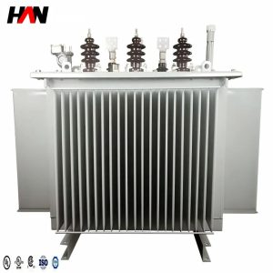
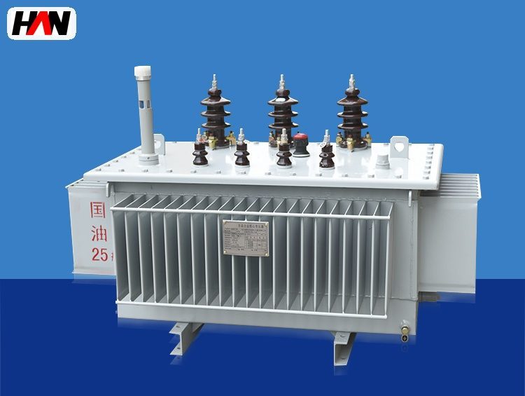
Sealed tank, low no-load loss for plant auxiliary power
Overview
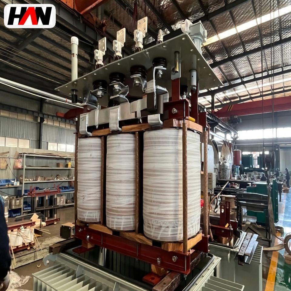
An amorphous oil-immersed transformer combines two well-proven ideas: a distribution transformer cooled and insulated by oil, and a magnetic core wound from amorphous alloy ribbon instead of grain-oriented silicon steel. The combination is used for plant auxiliary power, where a unit stays energised for years while carrying only a fraction of its rating. Typical duties are the yard distribution board, the dedusting fan substation, the water treatment plant, the compressed air station and the small 35 kV to 400 V points that feed a workshop without a full substation building. Rated from 30 kVA to 2500 kVA at 10 kV, 20 kV or 35 kV, the unit is a direct replacement for a conventional silicon steel design on the same foundation and the same cable.
The tank is the second half of the design. Instead of a conservator with a breather and a silica gel pot, the unit uses a sealed corrugated tank: the corrugations flex as the oil expands and contracts, so the oil never contacts the outside air and the transformer needs no oil top-up in normal service. For a plant that operates for years between shutdowns, and for a site where maintenance crews are already stretched across a melt shop, that simplification matters as much as the loss figure. HANI Metallurgy builds these units to IEC 60076-1 and GB 1094.1, with the same winding and testing discipline used on the continuous casting auxiliary supplies on the same site.
Technical Parameters
| Parameter | Unit | 200 kVA | 630 kVA | 1600 kVA |
|---|---|---|---|---|
| Rated capacity | kVA | 200 | 630 | 1600 |
| Primary voltage | kV | 10 | 10 | 35 |
| Secondary voltage | V | 400 | 400 | 400 |
| No-load loss | W | 190 | 400 | 900 |
| Impedance voltage | % | 4.5 – 6 | ||
| Vector group | — | Dyn11 | Dyn11 | Dyn11 |
| Cooling | — | ONAN | ONAN | ONAN |
| Tank type | — | sealed corrugated, no conservator | ||
| Protection | — | IP54 (sealed) | ||
| Efficiency at full load | % | 98.5 – 99.1 | ||
| Design standard | — | IEC 60076-1 / GB 1094.1 | ||
Typical values for reference. Final capacity, losses and impedance are confirmed by the routine test report and the approved project datasheet.
How It Works Under Furnace Duty
A plant auxiliary transformer is energised from the day the plant is commissioned to the day it is shut down, and for most of that time the load is a fraction of the nameplate. Under that profile the no-load loss is the largest single item in the transformer’s energy account. Amorphous alloy reduces that loss because the material has no grain boundaries to impede domain wall movement, so a smaller part of the magnetising energy is converted into heat on every cycle. The designer can either take the saving or trade it for a lower flux density and a quieter unit; in a plant yard the second option is often the better one.
The sealed corrugated tank changes the maintenance logic rather than the electrical one. In a conventional unit the oil expands into a conservator, air is drawn in and out through a breather, and moisture gradually enters the oil. In the sealed design the corrugated wall itself absorbs the expansion, so the oil volume is closed. The tank is filled and sealed under vacuum at the factory, and it stays sealed in service. Pressure inside the tank therefore varies more with load and ambient temperature than in a free-breathing unit, which is why the corrugation depth, the wall thickness and the weld quality are the critical manufacturing points, and why the routine test includes a pressure tightness check.
The 35 kV to 400 V variant is worth a separate note, because it removes a voltage level rather than adding one. Where a plant has a 35 kV ring and a group of loads within a few hundred metres, one 35 kV transformer at the load centre is often cheaper than a 35 kV distribution board plus several 10 kV units. The trade-off is that the 35 kV cable termination, the protection and the clearance distances have to be right at the transformer, so the unit is normally supplied with an IP54 enclosure and a cable box sized for the incoming cable.
Engineering notes
1. A sealed tank is not a maintenance-free tank: the pressure relief device, the oil level indicator and the gasket condition still have to be checked at each shutdown.
2. Never open a sealed unit to top up oil. If the level is low, the leak is the fault, not the level.
3. Loss comparison must include load loss, because an amorphous core saves on the standing term only.
Key Advantages
- Low standing loss: the amorphous core reduces no-load loss substantially against a conventional silicon steel core, and that is the loss that runs during every idle hour of the plant year.
- Sealed corrugated tank: no conservator, no breather, no silica gel and no oil top-up, so the oil stays dry and the maintenance routine stays short.
- Outdoor-ready: an IP54 sealed enclosure with a gasketed cover allows direct installation in a yard, on a plinth, without a building.
- Oil cooling with thermal reserve: the oil circuit carries overload and short-time peaks far better than a dry-type unit, which suits pump and fan starting duty.
- Drop-in replacement: the same footprint, vector group and voltage ratio as a conventional distribution unit, so an upgrade does not require new cables or a new foundation.
Selection and Commissioning
- Confirm the load profile is truly light. The economic case rests on hours energised at low load; a unit that runs near nameplate most of the day gains little from the core material.
- Fix the voltage level at the load centre. Choose 35 kV direct to 400 V where the ring is 35 kV and the loads are clustered; keep 10 kV where an existing board already serves the area.
- Check the fault level and the impedance. A low impedance passes more fault current to the downstream board, so the switchgear rating and the transformer impedance are chosen together.
- Specify the enclosure for the yard. IP54 sealed, cable box entry from below, a pressure relief device facing away from walkways and a plinth height that keeps the tank above standing water.
- Wire the protection signals. Winding temperature, oil temperature and the pressure relief contact should reach the plant control system; a sealed unit gives no visual warning before a fault.
- Commission with a pressure and loss record. Log the factory pressure test, the measured no-load loss and the oil temperature after a full load run, and keep them as the reference for later comparison.
Frequently Asked Questions
Q1: How do you top up oil in a sealed tank?
A: You do not. The tank is filled and sealed under vacuum at the factory, and the corrugations accommodate the expansion. A low oil level means a leak, so the correct action is to locate and repair it, then refill and re-evacuate rather than adding oil through an opened cover.
Q2: Can it be installed outdoors?
A: Yes, the sealed design with an IP54 finish is intended for outdoor installation on a plinth. Provide a cable entry that stays dry, keep the pressure relief device clear, and check that the plinth drains so the tank base does not stand in water.
Q3: The no-load loss is low, but what about load loss?
A: Load loss is comparable to a conventional unit of the same rating, because it is set by the winding design rather than by the core. The saving is on the standing term only, which is why the profile has to be checked before the extra cost of the core is justified.
Q4: Does service life differ from a conventional oil transformer?
A: The insulation system and the oil are the same family, so the life expectation is set by temperature and moisture rather than by the core material. A sealed tank keeps moisture out, which is an advantage, but the winding hot spot still has to be kept within its class limit.
Plan Auxiliary Power Around the Real Load
Send the load list, the incoming voltage and the installation site, and HANI Metallurgy will propose a sealed amorphous unit with the losses and protection that fit the duty.