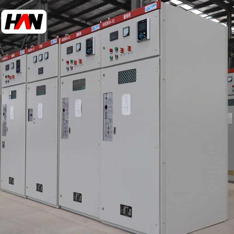
Description
40.5 kV Armored Switchgear
35 kV distribution and transformer feeders for melt shops
Overview
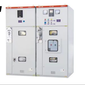
A 40.5 kV armored switchgear assembly is the switchboard that distributes power on a 35 kV network. 35 kV is the voltage level most often found on the primary side of an electric arc furnace transformer or a submerged arc furnace transformer, so this board usually sits directly upstream of the equipment that melts the steel. A 35 kV system is operated with 40.5 kV rated equipment, because 40.5 kV is the standard insulation level above 35 kV.
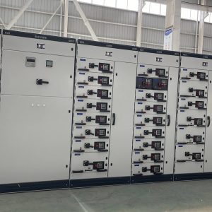
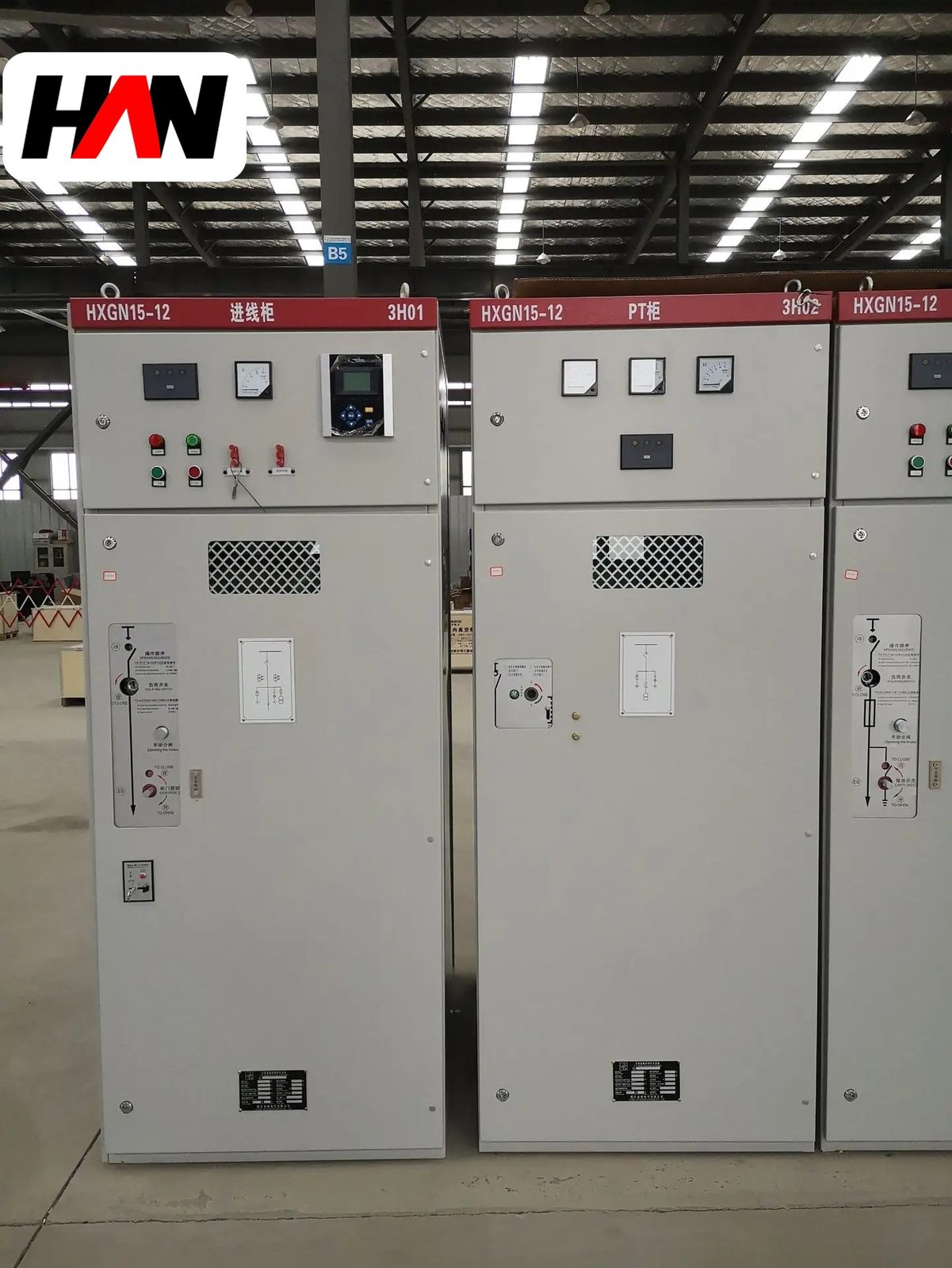
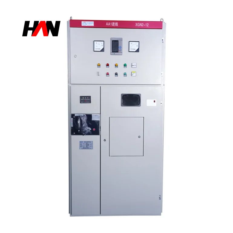
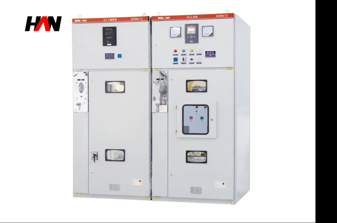
The construction is armored and metal-clad: earthed metal partitions divide the busbar, the withdrawable breaker, the cable and the low-voltage compartments, and the circuit breaker travels on a truck that is racked between test and service positions by a mechanical mechanism. HANI Metallurgy builds this family with a busbar rated from 630 A to 2000 A, a short-time withstand of 25 to 31.5 kA for 4 s and a lightning impulse level of 185 kV, to IEC 62271-200. Typical applications are the incoming feeder from the plant main substation, the busbar section between two transformer groups, and the feeders that supply a furnace transformer, a ladle furnace transformer or a large auxiliary transformer.
Technical Parameters
| Parameter | Unit | 630 A | 1250 A | 2000 A |
|---|---|---|---|---|
| Rated current | A | 630 | 1250 | 2000 |
| Rated voltage | kV | 40.5 | 40.5 | 40.5 |
| Short-time withstand, 4 s | kA | 25 | 31.5 | 31.5 |
| Peak withstand | kA | 63 | 80 | 80 |
| Lightning impulse withstand | kV | 185 | 185 | 185 |
| Power-frequency withstand, 1 min | kV | 95 | 95 | 95 |
| Main busbar | A | 630 – 2000, tubular or triple-bar copper | ||
| Circuit breaker | — | vacuum, withdrawable truck, motor-charged spring | ||
| Protection degree, enclosure | — | IP4X | ||
| Service continuity | — | LSC2B, armored, single busbar | ||
| Design standard | — | IEC 62271-200 | ||
Typical values for reference. Final ratings, fault level and cable terminal type are confirmed on the nameplate and the approved project datasheet.
How It Works Under Furnace Duty
The physical difference between this board and a 12 kV one is clearance. At 185 kV impulse and 95 kV power frequency, the air gap from phase to phase and from phase to earth is roughly double, and the insulation supports are taller. The result is a cubicle that is wider and deeper than a 12 kV unit of the same current rating, and a room that must be planned around those dimensions from the first layout drawing rather than at the end of the project. Inside the cubicle the same five compartments apply: busbar, riser, breaker truck, cable and low-voltage instrument section, each with its own pressure relief.
The five interlocks are the same set as on any metal-clad board, and they matter more here because the energy behind them is larger. The breaker cannot be closed unless the truck is in service or test and the earthing switch is open. The truck cannot be racked while the breaker is closed. The earthing switch cannot be closed with the truck in service. The cable compartment door is locked until the earthing switch is closed. And the truck cannot be racked from test to service while the earthing switch is closed. Each is a mechanical linkage; none of them depends on a relay being healthy.
Cable termination is the part that decides whether the board survives its first year. At 35 kV the termination is a stress cone, either cold-shrink or heat-shrink, and it must be built at the correct height above the gland plate so that the screen cut is inside the earthed zone and the cores reach the bushings without tension. The termination is then proof-tested before the cubicle is closed up. On the protection side, the feeder relay works with the transformer protection: differential for the transformer itself, Buchholz and winding temperature for internal faults, and an overcurrent stage that is set above the transformer inrush but below the downstream fault level. Where the transformer is rated 35 kV and fed directly from this board, that coordination is drawn on one sheet with both relay curves on it, which is the only way to see a gap before it becomes a trip that takes out the section.
Engineering notes
1. Buy the room with the board: a 40.5 kV cubicle needs more aisle and door width than the 12 kV layout it replaces.
2. Terminations are made on site by a certified jointer and proof-tested before the compartment is closed; a badly built stress cone fails at the first switching surge.
3. Transport sections are split at busbar joints, so the joint bolts, the insulating boots and the torque values travel with the shipment.
Key Advantages
- Correct level for a 35 kV furnace feeder: 185 kV impulse and 95 kV power-frequency withstand are matched to the insulation coordination of a 35 kV transformer primary, including the surge arrester characteristics.
- Armored, five-compartment structure: earthed metal partitions and individual pressure relief keep an internal arc away from the operating aisle and away from the adjacent feeders.
- Interlocks that work without power: the racking and earthing sequence is enforced mechanically, which is the state the board is in when an operator is most likely to make a mistake.
- Cable compartment for stress cones: the depth and the gland plate position are set so a screened termination can be built at the correct height with the cores relaxed.
- Split for transport and site assembly: the lineup ships in sections with the busbar joints prepared in the works, so site work is bolting, torqueing and testing rather than fabrication.
Selection and Commissioning
- Set the fault level from the source. Transformer impedance and cable impedance from the main substation decide the prospective current; the board rating is chosen above it, with the peak value sizing the supports.
- Choose the terminal type early. Cold-shrink or heat-shrink, single-core or three-core, and the cable screen arrangement all change the compartment height and the support positions.
- Coordinate with the transformer protection. Differential, Buchholz, winding temperature and overcurrent are plotted together against the upstream relay, and the grading margin is checked at the maximum and the minimum fault level.
- Plan the transport split. Sections are limited by shipping width and by the door of the electrical room; the split points are agreed with the busbar joint design.
- Check the earthing and the floor. The earth bar is bonded at both ends of the lineup and the floor loading of a 40.5 kV cubicle is higher than a low-voltage board of the same footprint.
- Commission in sequence. Mechanical interlock check, then insulation resistance, then power-frequency withstand on the cables, then primary injection, then a no-load closing test on the transformer before the first heat.
Frequently Asked Questions
Q1: Why is a 40.5 kV cubicle so much wider than a 12 kV one?
A: Because the air clearance needed to hold 185 kV impulse and 95 kV power frequency is roughly twice that at 12 kV, and the insulation supports are taller. The current rating hardly changes the width; the voltage class does.
Q2: Why is 40.5 kV equipment used on a 35 kV system?
A: Equipment is rated by its highest voltage for equipment, and 40.5 kV is the standard level above 35 kV. Using the 40.5 kV level gives margin for supply voltage excursions, switching transients and the voltage rise on an earth fault in an ungrounded network.
Q3: Can the board be installed outdoors?
A: Not as a standard indoor cubicle. Outdoor installation needs a weatherproof enclosure or a prefabricated substation with ventilation, heating and a walk-in aisle. In a smelting plant the usual arrangement is an indoor electrical room close to the furnace, because the cable run to the transformer is short and the maintenance is frequent.
Q4: How is the on-site dielectric test done?
A: Each cable and each phase is tested separately with the transformer and the surge arresters disconnected, at the test voltage agreed in the project specification, for one minute. Insulation resistance and a partial discharge check follow, and the results are recorded against ambient conditions so that a later comparison is meaningful.
Build the 35 kV Section Around the Furnace
Send the incoming fault level, the transformer ratings, the cable types and the room dimensions, and HANI Metallurgy will return a 40.5 kV lineup with the compartments, terminals and protection coordination fixed.