Description
LV Switchgear for Continuous Casting
Draw-out feeders for casting drives and secondary cooling
Overview
A continuous casting line is fed from a low-voltage switchboard that sits between the casting transformer and the drives of the machine. The loads are unusual for a low-voltage board: mould oscillation motors, withdrawal and straightening drives, secondary cooling water pumps, torch cutting machines, roller tables and, on many machines, an electromagnetic stirring supply. They are grouped in one lineup because they must start in a fixed sequence and stop in a fixed sequence, and because the casting speed signal that coordinates them comes from a single controller. The board, in other words, is part of the process, not only part of the electrical infrastructure.
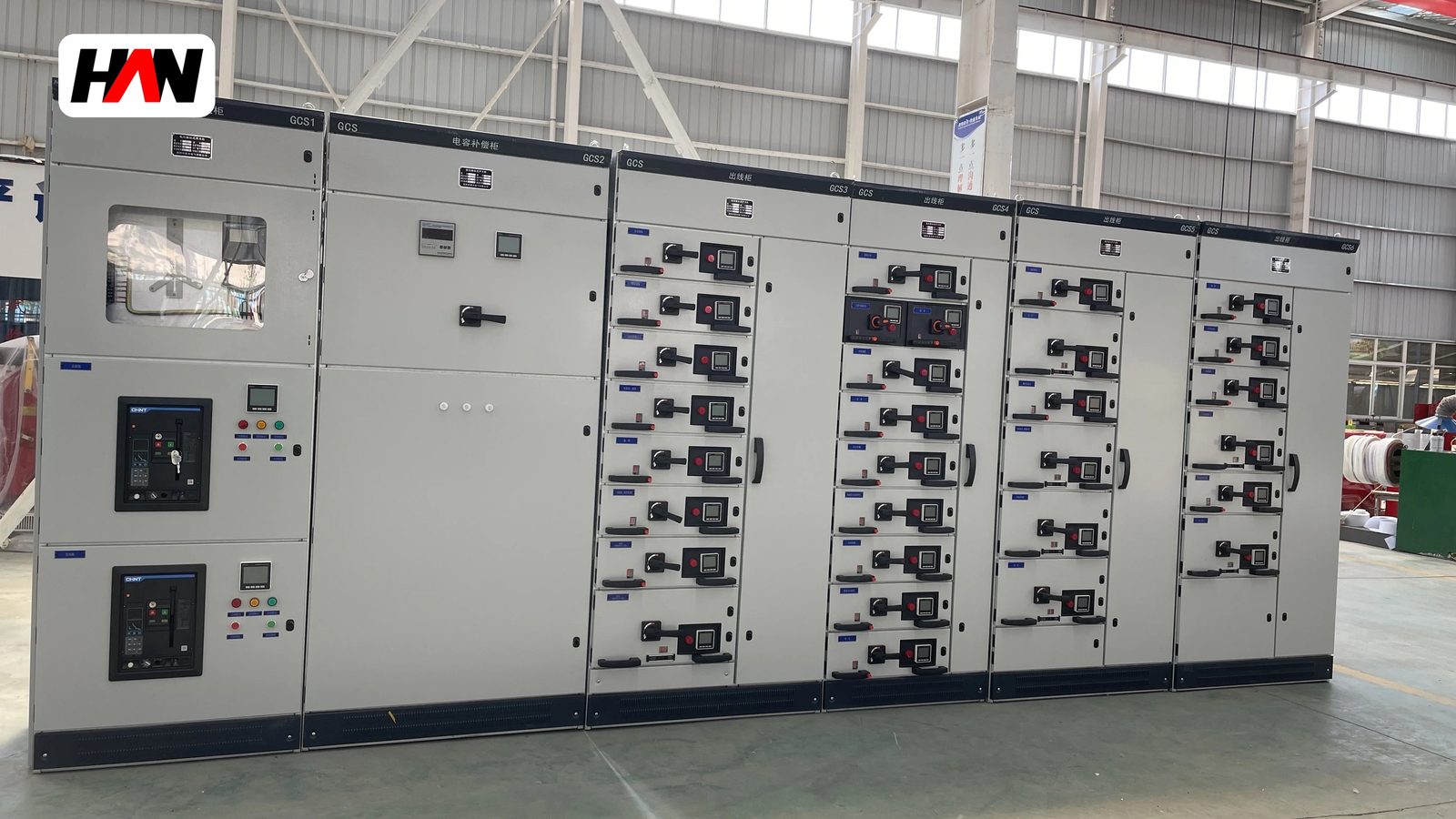
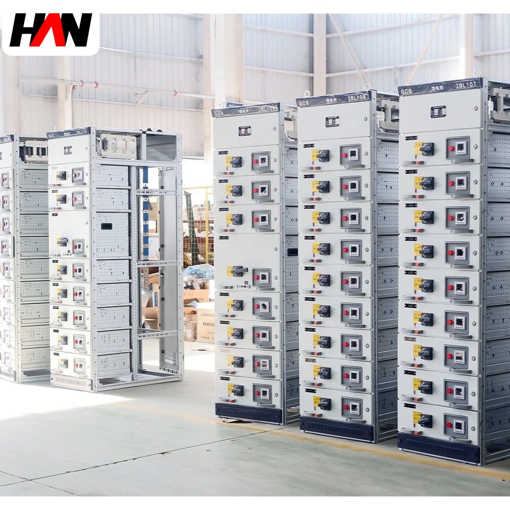
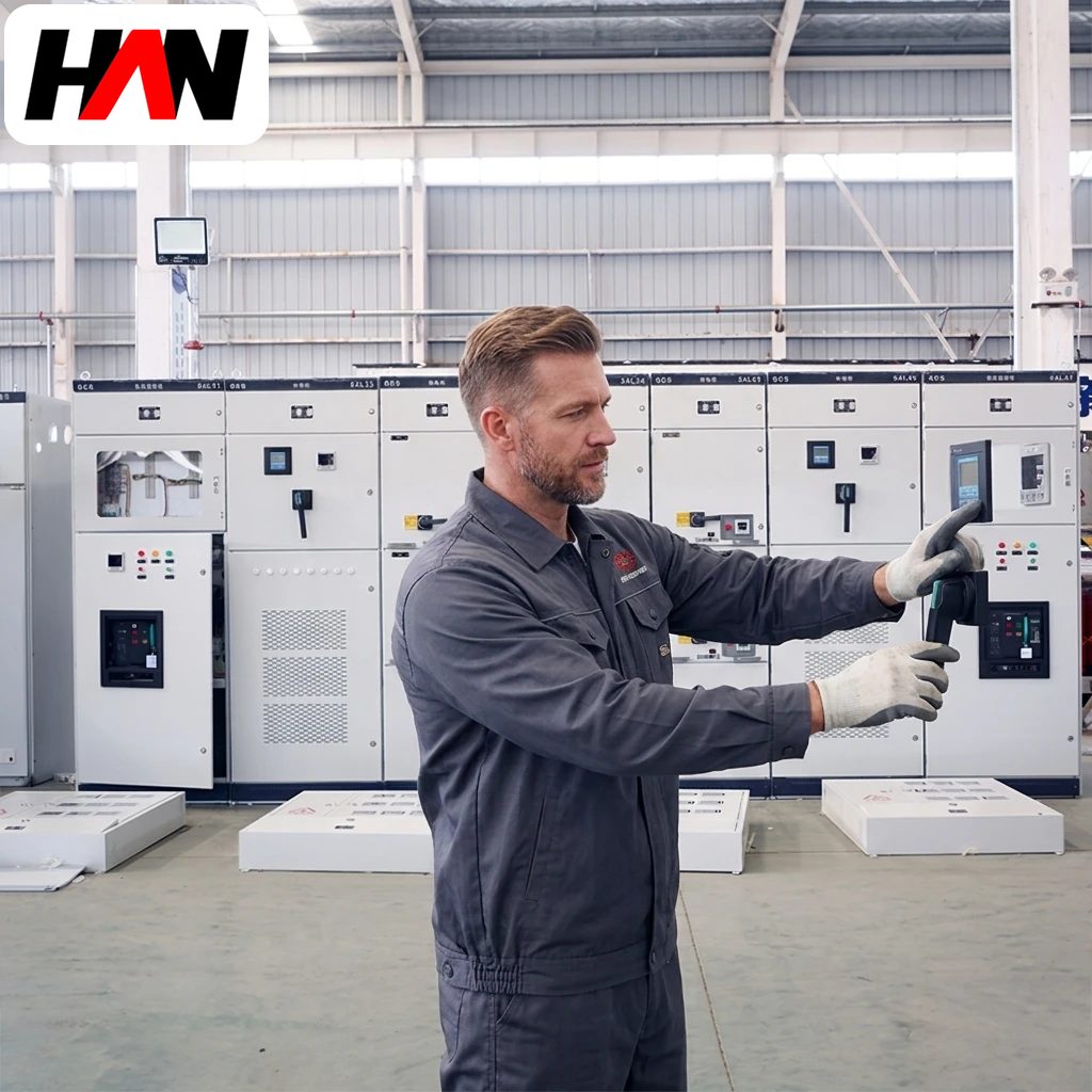
The GCS system is a draw-out low-voltage assembly built for this role. Busbar current runs from 1000 A to 4000 A at 400 V or 690 V, short-time withstand is 50 to 80 kA, and the functional units are withdrawable so that a failed feeder can be replaced while the rest of the lineup continues to run. A caster casts a sequence of heats without stopping, so the difference between a five-minute module change and a two-hour cable re-termination is the difference between a scarfed strand and a lost sequence. HANI Metallurgy supplies these boards as part of the billet continuous casting machine electrical package, together with the motor control centres downstream.
Technical Parameters
| Parameter | Unit | 1000 A | 2500 A | 4000 A |
|---|---|---|---|---|
| Busbar rated current | A | 1000 | 2500 | 4000 |
| Rated operational voltage | V | 400 / 690 | ||
| Short-time withstand current Icw | kA / 1 s | 50 | 65 | 80 |
| Peak withstand current Ipk | kA | 105 | 143 | 176 |
| Drawer module height | E | 8E / 16E / 24E | ||
| Form of separation | — | Form 3b / 4b | ||
| Protection degree | — | IP31 to IP42 | ||
| Functional unit | — | Draw-out, connected / test / disconnected | ||
| Busbar material | — | Tinned copper | ||
| Design standard | — | IEC 61439-2 | ||
Typical values for reference. Final ratings, form of separation and feeder schedule are fixed on the nameplate and the approved project datasheet.
How It Works Under Furnace Duty
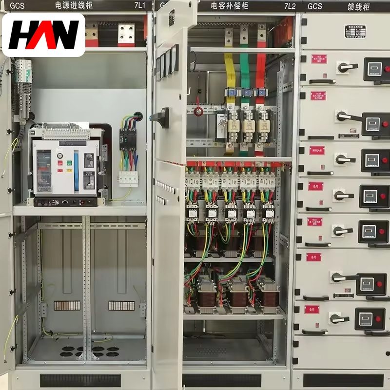
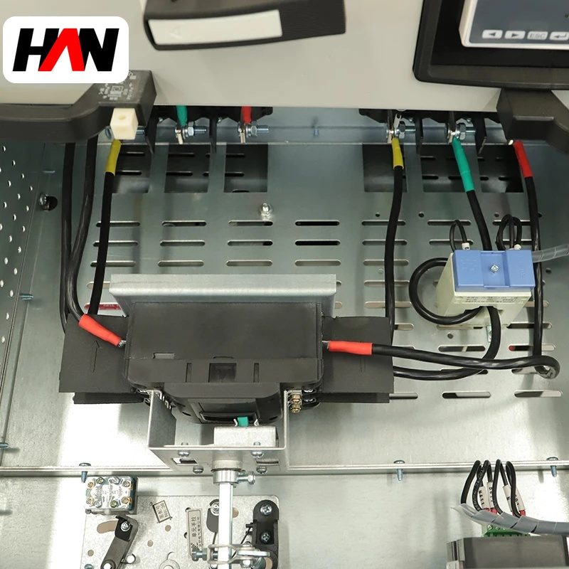
Each feeder is a withdrawable unit built on an 8E grid, where one module is 200 mm of vertical space in 25 mm steps. The unit carries the breaker or the contactor, its protection and its terminal block as one assembly that slides on rails into the section. In the connected position the main and auxiliary contacts are engaged; in the test position the control circuit stays live while the main circuit is isolated, which is how a casting drive is proved without the machine moving; in the disconnected position the unit comes out on a trolley. Coding pins stop a unit of the wrong rating from being inserted, and the crank is interlocked so the unit cannot be moved while the breaker is closed.
Form 4b is the reason this construction matters on a caster. The busbar is separated from the functional units, each functional unit is separated from its neighbours, and the terminals of each unit are separated from the terminals of the others as well as from the busbar. That means a unit can be worked on, or its cable replaced, with the rest of the lineup energised and without exposing the adjacent feeder. Form 3b keeps the busbar separation but not the terminal separation, and it is the usual choice for the less critical sections. The difference is not cosmetic; it decides whether a cable termination can be touched during a live sequence.
Thermally, the board sits in a caster electrical room where the ambient is high and the air carries scale dust. IEC 61439-2 verifies the assembly by temperature rise, and that verification is bound to the ambient of the test, so the incoming current is derated for the room. Secondary cooling pumps run continuously and are usually on drives with a pressure loop; the withdrawal and straightening drives draw high torque at low speed and their converters lose more heat than their rating suggests. Electromagnetic stirring adds a low-frequency, high-current load whose waveform is not sinusoidal, so the harmonic current is declared to the compensation and protection study before the board is built.
Engineering notes
1. Feeder assignment follows the casting sequence: mould, secondary cooling, withdrawal, cutting, run-out. Losing one group should not take the strand out.
2. Icw and Ipk are set by the fault level at the caster board, which is fixed by the casting transformer and its cable run, not by the connected load.
3. The interface to the caster PLC is a mix of hard-wired permissives and a fieldbus for status, because a permissive that stops the machine must not depend on a network.
Key Advantages
- Module change instead of repair: a failed feeder is exchanged for a spare on a trolley in minutes, which is what a casting sequence actually needs.
- Form 4b compartmentation: terminals, functional units and busbar are separated, so work on one feeder does not expose the one beside it.
- Test position for drive proving: controls stay live while the main circuit is isolated, so rotation, permissives and set points are checked before the machine is allowed to move.
- Short-time and peak ratings for a stiff supply: 50 to 80 kA withstand with 105 to 176 kA peak covers the fault level of a dedicated casting transformer.
- Grouped by process: the feeder schedule mirrors the casting sequence, so a fault isolates one function instead of the whole strand.
Selection and Commissioning
- Map the casting sequence. List every drive with its starting method and its role in the strand, then group the feeders so that one section never carries two functions that must not stop together.
- Fix the fault level first. The casting transformer rating and the cable length set Icw and Ipk; confirm both values and the withstand duration against the upstream device curve.
- Choose the form of separation deliberately. Form 4b for feeders that may be maintained during a sequence, form 3b for sections where a shutdown is acceptable.
- Reserve modules. Leave 8E and 16E spare capacity in each section; a caster is modified more often than a substation.
- Plan the heat and the dust. Verify room ventilation, specify filtered ventilation where scale dust is heavy, and keep drive compartments on their own airflow.
- Commission against the PLC. Point-to-point check of every hard-wired permissive, a trip test of each feeder, and a simulated sequence with the dummy bar before the first real cast.
Frequently Asked Questions
Q1: Why does a casting line need draw-out switchgear rather than a fixed board?
A: Because the machine runs sequences. A fixed board means a cable re-termination and a section shutdown to replace one breaker; a draw-out board means a module change while the other feeders keep the strand alive.
Q2: How is a pump failure kept from stopping the cast?
A: By putting the secondary cooling pumps in a group with one installed spare, by auto-transferring the duty pump on pressure loss, and by keeping the feeder modules interchangeable so the electrical side can be restored quickly. The control logic decides the transfer; the board decides how fast it can be repaired.
Q3: What does electromagnetic stirring demand from the distribution board?
A: A dedicated feeder with a non-sinusoidal current, its own harmonic assessment and a supply that does not share a weak section with instrumentation. The stirring supply also produces a strong stray field, so cable routing and steelwork near the feeder need attention at the layout stage.
Q4: What is the practical benefit of form 4b?
A: Terminals are separated as well as functional units. A cable can be isolated and re-terminated in one compartment without opening the one next to it, which is the difference between planned maintenance and an unplanned outage on a live lineup.
Design the Caster Board Around the Sequence
Send the drive list, the casting sequence and the fault level at the caster transformer, and HANI Metallurgy will return a feeder schedule, a form of separation and an outline layout.