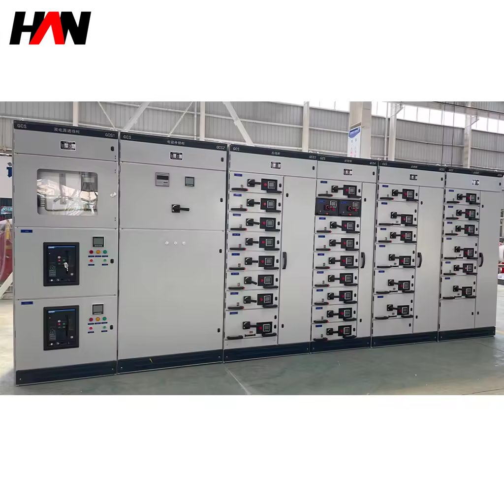
Description
GGD Fixed LV Switchgear
Simple, robust distribution close to the furnace
Overview
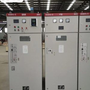
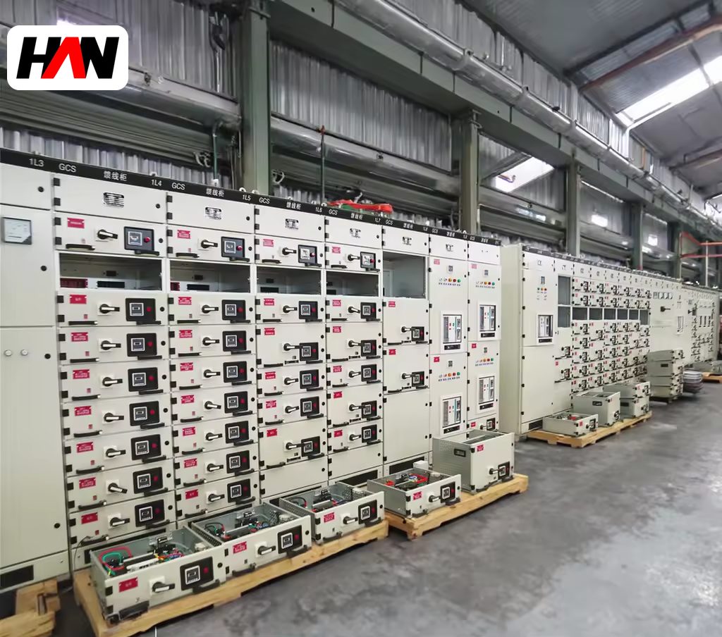
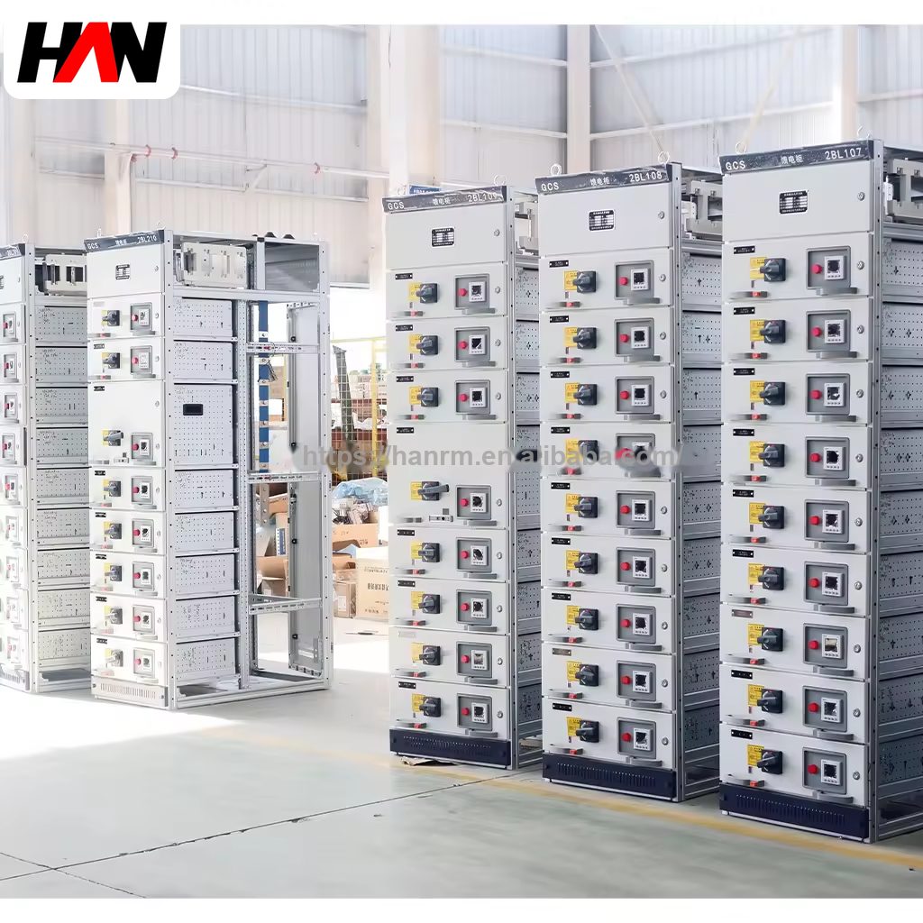
A GGD board is a fixed, single-front low-voltage switchgear assembly. The devices are bolted to a frame inside the section, the busbar runs at the top or the rear, cables enter from the bottom, and everything is reached from the front door. There is no withdrawable carriage and no plug-in contact: the breaker is connected with bars and lugs. That simplicity is the point. The board carries up to 3150 A at 400 V, withstands 50 kA for one second with a 105 kA peak, and does so with fewer parts than a draw-out system, which makes it the cheapest way to distribute power to a group of loads that do not change.
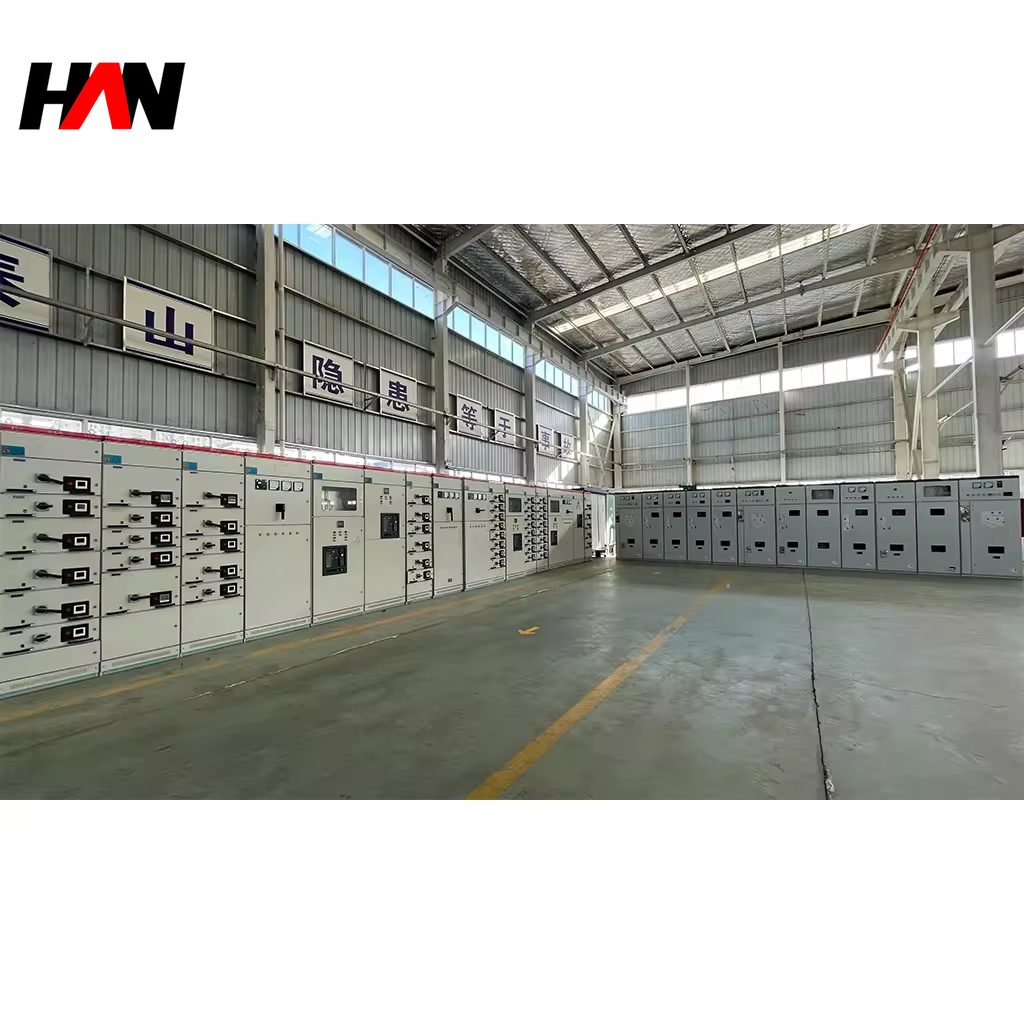
Around a furnace those loads are the auxiliaries. Hydraulic power packs, water treatment and recirculation, small ventilation fans, the local lighting and welding sockets, the compressed air dryer, the service distribution to the pouring floor. None of them needs a motor control centre of its own, and none of them is switched often. What they need is a short cable route, a robust enclosure that survives a hot and dusty room, and protection that is easy to isolate for a repair. HANI Metallurgy applies this board as local distribution downstream of the main low-voltage board of an electric arc furnace melt shop, in the electrical room or in a bay close to the equipment it feeds.
Technical Parameters
| Parameter | Unit | 1000 A | 2000 A | 3150 A |
|---|---|---|---|---|
| Busbar rated current | A | 1000 | 2000 | 3150 |
| Rated operational voltage | V | 400 | ||
| Short-time withstand current Icw | kA / 1 s | 50 | ||
| Peak withstand current Ipk | kA | 105 | ||
| Outgoing ways per section | — | 8 to 24 | ||
| Protection degree | — | IP30 to IP40 | ||
| Construction | — | Fixed, single-front | ||
| Busbar material | — | Copper flat bar | ||
| Incoming device | — | Air circuit breaker or moulded case breaker | ||
| Design standard | — | IEC 61439-2 | ||
Typical values for reference. Final ratings, way count and device schedule are fixed on the nameplate and the approved project datasheet.
How It Works Under Furnace Duty
The layout is vertical. The horizontal busbar is at the top of the section, the distribution bars drop down the rear, and the outgoing devices sit in a row behind the front door with the cable terminals below them. Because there is no carriage, the device can be bolted close to the busbar, and the bar length between the incomer and the busbar is short, which keeps the voltage drop and the stray field low. The trade-off is maintenance: a failed breaker has to be unbolted and its cables disconnected, so the section has to be shut down. On a board that feeds lighting, sockets and a standby pump, that is an acceptable trade, and it is the reason the fixed design survives in the furnace area at all.
Heat is the constraint that decides the real rating. A copper busbar of 3150 A in free air is one section; the same bar inside a closed steel enclosure is another, because the enclosure traps the heat and the wall temperature adds to the ambient in the room. IEC 61439-2 verifies the assembly by a temperature rise test, and that test is run at a stated ambient, so a board installed in a room next to a furnace where the air is well above that figure must be derated before it is ordered. Ventilation louvers, a raised base, a fan section or a larger bar are the usual answers, and the bar is often increased one size rather than adding fans, because a fan is one more item that stops when the air is dusty.
Protection is arranged in two levels. The incomer is a breaker with an adjustable long-time setting and a short-time setting that is coordinated with the devices upstream, so a fault on one outgoing way does not trip the whole board. The outgoing ways use moulded case breakers or fuse-switch combinations, chosen by cable size and by the duty of the load. The door and the incomer are interlocked: the main breaker must be open before the front door can be opened, and the busbar is screened behind a barrier so that a live section cannot be reached while the door is open. Every section carries a phase indication and a labelled single-line diagram on the inside of the door, because a board close to a furnace is operated by whoever is on shift.
Engineering notes
1. Single-front construction allows the board to stand against a wall; allow space at the front for a door swing and at the top for cable entry.
2. Icw of 50 kA for one second belongs to the assembly, not to the breakers; the outgoing devices must be able to withstand it too.
3. A fixed board has no test position. Prove the load before it is connected, because the alternative is proving it live.
Key Advantages
- Lowest cost per outgoing way: no carriage, no plug-in contacts and no coding hardware, so the same budget buys more feeders and a larger busbar.
- Short, direct busbar runs: the devices sit close to the bar, which reduces voltage drop and keeps the impedance low for motor starting.
- Rugged in a hot room: fewer moving parts, no drawer mechanism to seize in dust, and a frame that tolerates the vibration of a melting bay.
- Wall-standing footprint: single-front access means the board can be pushed back against a wall, which matters when floor space beside the furnace is scarce.
- Clear isolation for repair: door interlocking with the incomer and screened busbar make a safe shutdown a matter of one operation, not a procedure.
Selection and Commissioning
- Confirm the load is stable. A fixed board suits loads that will not be re-assigned every year; if the bay is expected to change, a draw-out assembly is cheaper over its life.
- Size the busbar for the real ambient. Take the room temperature in summer, derate the 3150 A frame accordingly, and write the derated figure into the datasheet.
- Check Icw against the source. The 50 kA rating must exceed the prospective fault at the board, and the outgoing devices must be rated for the same value.
- Plan the cable entry. Bottom entry with a removable gland plate, and enough depth in the cable zone for the largest conductor and its bending radius.
- Coordinate the protection. Set the incomer above the largest outgoing way with a time margin, and check the earth fault path through the enclosure and the PE bar.
- Commission cold, then hot. Insulation test, torque check of every bar joint, then a temperature survey of the busbar and terminals under load before the board is handed over.
Frequently Asked Questions
Q1: How do I choose between a fixed board and a draw-out one?
A: By how often the feeders will be maintained or changed. Stable auxiliary loads with a planned shutdown favour the fixed board; drives that must be replaced during production, or a bay that will be re-assigned, favour the draw-out board despite the higher price.
Q2: Does maintenance on a fixed board always mean a full shutdown?
A: Replacing a device means isolating that section, and often the incomer, because the devices are bolted to the busbar. Isolation of one outgoing way for a cable change is normally possible without touching the others, which is what most maintenance actually needs.
Q3: How is a 3150 A busbar kept cool inside an enclosure?
A: By cross-section first, by arrangement second. Multiple bars per phase with an air gap between them, a short path to the outgoing devices, ventilation openings sized for the loss, and a base that lets air in from below. Forced cooling is added only where the room itself is the problem.
Q4: Can the board be installed against a wall?
A: Yes. That is the purpose of single-front construction: access, cable termination and operation all happen from the front. Leave room for the door swing, for top or bottom cable entry, and for the ventilation openings at the rear to stay clear.
Distribute Power Where the Furnace Needs It
Send the auxiliary load list, the room temperature and the fault level, and HANI Metallurgy will return a section arrangement, a device schedule and a derated rating.