Description
Single-Phase Furnace Transformer
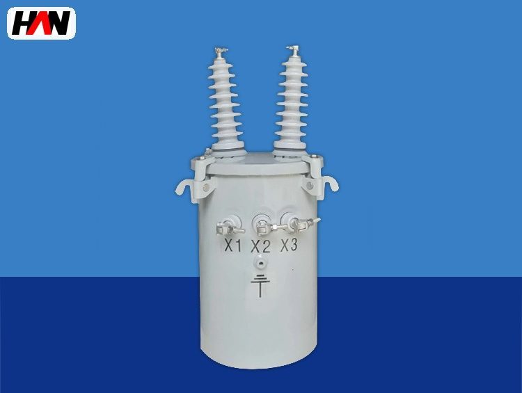
Three-unit banks for large submerged arc furnaces
Overview
A single-phase furnace transformer is one unit of a three-unit bank that supplies a large smelting furnace. Each unit feeds one electrode, the three units are connected in delta or star on both sides, and together they deliver the same three-phase power that a single three-phase transformer would. The reason for splitting the duty is physical rather than electrical: a 40 MVA three-phase furnace transformer is a transport problem, a lifting problem and a spare-parts problem, while three units of 5 MVA to 16 MVA each are ordinary heavy machinery.
Every unit in the family takes a 35 kV primary and delivers 120 V to 260 V at 42 kA to 130 kA. Each has its own on-load tap changer with 20 to 27 steps, its own protection and its own cooling circuit. That independence is the second reason the arrangement is popular: with separate taps, the three electrode currents can be trimmed against each other, which matters on a furnace where the burden is never perfectly symmetrical. HANI Metallurgy supplies these units as a matched set for a submerged arc furnace transformer installation, with the bank connection, tap schedule and protection scheme fixed as one package.
Technical Parameters
| Parameter | Unit | 5 MVA | 10 MVA | 16 MVA |
|---|---|---|---|---|
| Unit capacity | MVA | 5 | 10 | 16 |
| Primary voltage | kV | 35 | 35 | 35 |
| Secondary voltage range | V | 120 – 220 | 120 – 240 | 123 – 260 |
| Secondary current, lowest tap | kA | 42 | 83 | 130 |
| Impedance voltage | % | 5 – 7 | ||
| Tap changer | steps | 21, on-load | 24, on-load | 27, on-load |
| Cooling | — | ONAF | OFAF | OFAF |
| Core and winding type | — | Double-column parallel or shell type | ||
| Efficiency at full load | % | ≥ 98.6 | ≥ 98.9 | ≥ 99.1 |
| Design standard | — | IEC 60076-1 | ||
Typical values for reference. Final ratings, impedance and tap schedule are fixed on the nameplate and the approved project datasheet.
How It Works Under Furnace Duty
A three-unit bank is a three-phase circuit assembled from single-phase parts. With the low-voltage windings in delta, each unit carries the line current divided by the square root of three and the full line voltage; with the high-voltage windings in star, each unit sees phase voltage and the bank needs a neutral point. The choice is made on the furnace side, because the electrode circuit, the short net and the earthing arrangement belong to the furnace, and the transformer bank has to match what the furnace can accept. Coil geometry inside each unit also matters: a double-column parallel design splits the winding between two limbs to halve the flux per limb and shorten the magnetic path, while a shell type closes the flux around the coil and is favoured where the unit has to be short enough to fit under a roof.
Harmonics behave differently in a bank. Third-harmonic currents cannot flow in a star point that is not earthed, and they cannot flow in a delta without a circulating path, so a stabilizing winding or a delta-connected tertiary is provided inside the unit to keep the flux sinusoidal. A bank built from three single-phase cores has no inter-phase magnetic coupling, so the zero-sequence path is defined entirely by the connection and by that stabilizing winding. This is one reason a bank and a three-phase unit are not electrically interchangeable even when the nameplate ratings look the same.
Electrode current imbalance has several causes: unequal electrode depth, uneven burden distribution after charging, differences in contact-shoe condition, and a short net that is not geometrically symmetrical. With three independent tap changers the operator can offset a persistent imbalance by adjusting one phase by a step or two. That is a correction of a few percent, not a cure: if the imbalance comes from a bad contact shoe or a blocked chute, the electrical adjustment only hides it. Every unit still needs its own winding temperature and current supervision, because the loaded phase is the one that reaches its limit first.
Engineering notes
1. The three units of a bank are ordered as one set with matched impedance and matched tap schedule, because unequal impedance in one phase produces a permanent current offset.
2. Low-voltage terminals X1, X2 and X3 are arranged so that the delta or star links can be made inside the terminal chamber without crossing leads.
3. Each unit carries its own Buchholz, pressure relief, oil and winding temperature devices; a common trip is arranged at the feeder, not by sharing sensors.
Key Advantages
- Transportable by design: each unit stays inside normal road and crane limits, so a large furnace can be built without a special heavy-haul route or a site-assembled tank.
- One spare covers three positions: a single spare unit, identical in rating and tap schedule, can replace any phase, which is not possible with a three-phase tank.
- Phase-wise voltage trim: independent on-load tap changers let the operator correct a persistent electrode current offset by one or two steps on one phase.
- Short magnetic path: double-column parallel or shell-type construction keeps the unit low, which helps where the transformer room is under an existing roof beam.
- Simple maintenance access: smaller tanks, separate cooling and separate protection mean a single phase can be isolated and worked on while the bank is out of service on a planned basis.
Selection and Commissioning
- Divide the furnace power by three, then check the limits. The per-unit rating follows from the furnace capacity, but transport weight, lifting height and the available room often set the upper bound before the electrical design does.
- Fix the bank connection with the furnace builder. Delta or star, earthed or isolated neutral, and the available short-net geometry decide the terminal layout and the stabilizing winding.
- Keep the three impedances matched. Ask for the measured impedance of each unit on the test report and compare them before the bank is energised.
- Plan for single-phase isolation. The high-voltage arrangement needs a means of isolating one unit while the other two are proven dead, and the low-voltage links must be accessible for that work.
- Set protection per unit. Overcurrent, thermal image, Buchholz, pressure relief and temperature devices act on the common feeder trip but are set from each unit’s own data.
- Commission the bank as a bank. Phase sequence, tap position agreement and current balance are checked at several taps on charge, because a mistake in one unit’s polarity shows up as a current offset rather than as a failure.
Frequently Asked Questions
Q1: When should three single-phase units be chosen instead of one three-phase unit?
A: When the total rating pushes a three-phase tank beyond transport or lifting limits, when a single spare has to cover the installation, or when phase-wise tap adjustment is wanted. Below about 15 MVA total a three-phase unit is usually more compact and cheaper to install, with fewer connections to get wrong.
Q2: How is three-phase current imbalance corrected in a bank?
A: By stepping the tap changer of the loaded phase down or the light phase up, within the range the tap schedule allows. That corrects a few percent. Larger offsets come from electrode depth, contact shoes or burden distribution and have to be fixed mechanically, otherwise the correction simply moves the overload to another phase.
Q3: Can the furnace run on two units if one fails?
A: Only as an emergency measure and only at heavily reduced output, because the remaining two units form an open-delta connection with a different voltage and current relationship and with a large negative-sequence component. Protection settings and the electrode control have to be adjusted for it, so it is a planned contingency, not a normal operating mode.
Q4: What transport limits apply to one unit?
A: Unit weight, tank height and the position of the high-voltage bushings normally decide it, and the limits differ by route and by lifting equipment. Send the transport envelope with the enquiry; the winding layout and the tank shape can often be adjusted to stay inside it without changing the electrical rating.
Plan the Bank Around the Furnace
Send the furnace rating, the bank connection and your transport envelope, and HANI Metallurgy will return a per-unit rating and a matched tap schedule.