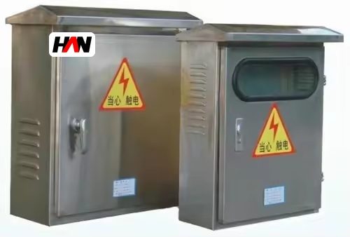
Description
PZ30 Final Distribution Board
Final circuits for control rooms and workshops
Overview
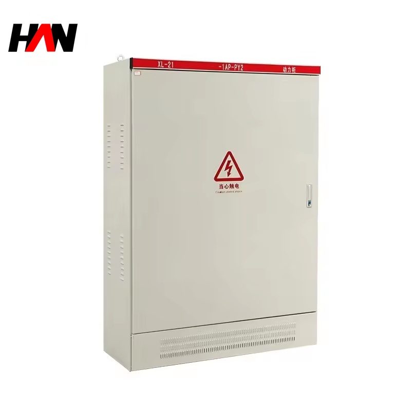
A PZ30 final distribution board is the last enclosure in the electrical chain of a melt shop. It takes a three-phase feed from a sub-distribution cabinet and splits it into final circuits: control room lighting, instrument and PLC supplies, maintenance sockets on the platform, small fans, valve supplies and the hand tools used during a shutdown. The board is built around a DIN rail, so the protective devices are modular breakers and residual current units that clip on and off without drilling. HANI Metallurgy builds the range from 12 to 45 ways with an incomer of 63 to 125 A at 230/400 V, assembled and routine-tested to IEC 61439-3.
Its position in the plant explains most of its design. A board in a control room is fed from a stable busbar, is opened twice a year and rarely sees a fault. A board at the foot of the furnace platform works in radiant heat and metallic dust, and is opened by an electrician who needs the circuit back in service before the next heat. Both are called final boards, yet the enclosure, the IP rating and the residual current arrangement have to be chosen separately for the two. This page sets out how ways, incomer and protection are matched to those two situations, and where the responsibility of the final board ends and that of the upstream electric arc furnace distribution begins.
Technical Parameters
| Parameter | Unit | 12 ways | 24 ways | 45 ways |
|---|---|---|---|---|
| Rated ways | ways | 12 | 24 | 45 |
| Incomer current | A | 63 | 100 | 125 |
| Rated voltage | V | 230 / 400 | 230 / 400 | 230 / 400 |
| Residual current sensitivity | mA | 30 | 30 | 30 |
| Protection degree | IP | IP30 – IP54 | IP30 – IP54 | IP30 – IP54 |
| Enclosure material | — | painted steel | painted steel | steel / stainless |
| Mounting | — | surface / flush | surface / flush | surface |
| Device mounting | — | DIN rail | DIN rail | DIN rail |
| Neutral and earth bars | — | separate | separate | separate |
| Design standard | — | IEC 61439-3 | ||
Typical values for reference. Final way count, incomer rating and protection degree are confirmed on the nameplate and the approved project datasheet.
How It Works Under Furnace Duty
The loads on a final board are small, but they are scattered and they are mixed. One way feeds the lighting of a control room, the next feeds a single-phase instrument supply, a third feeds a three-phase maintenance socket beside the furnace, and a fourth feeds the small fan that keeps a panel cool. When the lighting sits on one phase and the socket circuits sit on another, the board carries an unbalanced load and the neutral current returns through a bar that was chosen before the circuits were known. A good PZ30 layout starts with a phase schedule: single-phase ways distributed across the three phases, and each outgoing neutral landed on its own terminal rather than doubled into a shared hole.
Residual current protection is the second design task. A 30 mA device protects people on socket circuits, but a single device covering a whole group of ways will take the group down for the leakage of one appliance, and a long cable run in a damp trench carries enough capacitive leakage to sit close to the trip threshold before anything is plugged in. The workable arrangement keeps the sensitive device on the final circuits that people touch, keeps lighting and instrument supplies on circuits that a nuisance trip would not black out, and uses a time-delayed selective device at the incomer so that a fault is cleared at the smallest possible boundary.
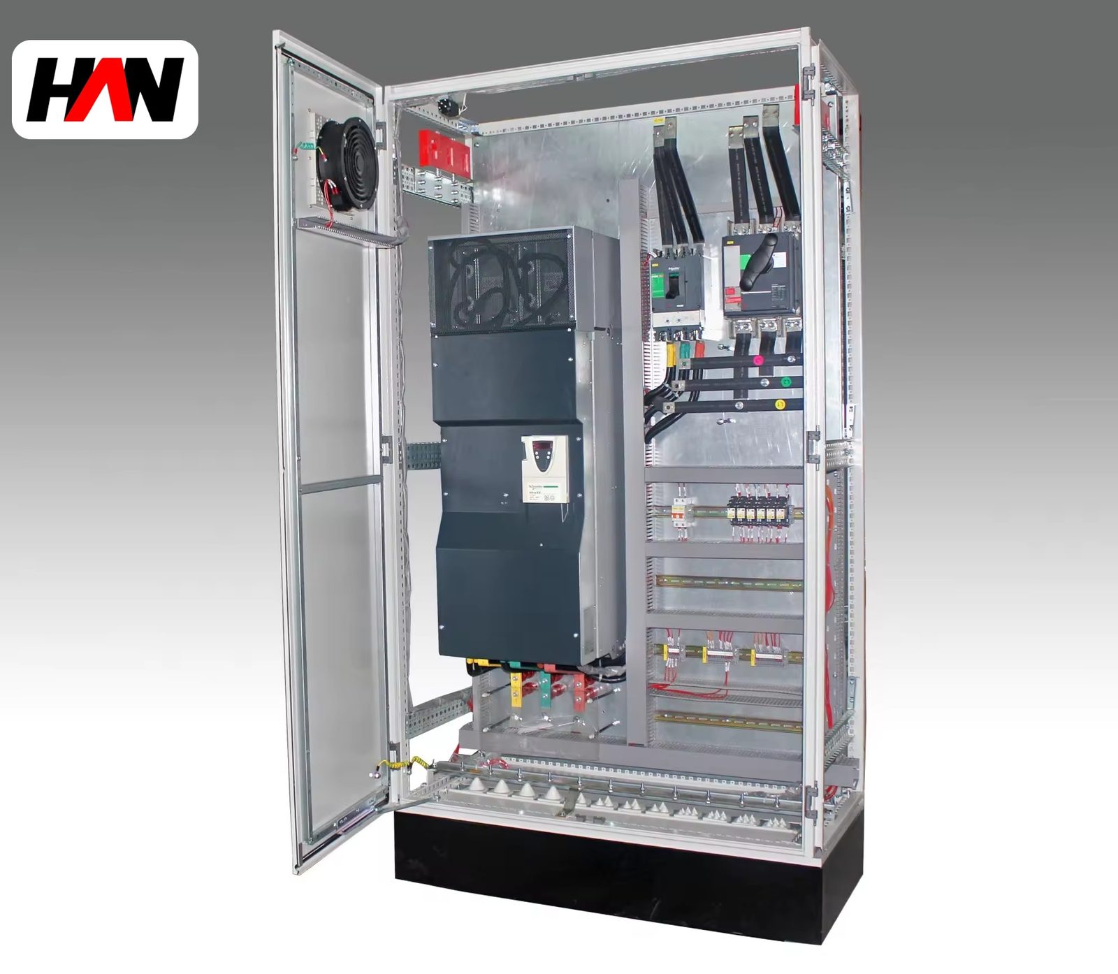
Heat is the third and most often ignored task. A modular breaker is a thermal device, and its rating is calibrated at a reference ambient temperature in free air. Inside a closed steel box, with a full complement of ways and a control room that runs warm in summer, the air around the breakers is well above that reference, and the device that was ordered as a 63 A incomer may only carry a fraction of its rating continuously.
Engineering notes
1. Leave spare ways at the end of each rail; a board filled to its last way has no thermal margin and no room for the next instrument supply.
2. Keep the neutral bar rating equal to the incomer, and never land two outgoing neutrals under one screw; a loose neutral in a final board is a fire risk, not a nuisance.
3. Write the circuit schedule inside the door and keep it current; a board opened in a hurry is only as safe as its labels.
Key Advantages
- One rail, any device: the DIN rail accepts breakers, residual current units, contactors and surge protection in the same footprint, so a circuit can be changed from a socket feed to a small motor feed without cutting the enclosure.
- Way count that fits the room: 12, 24 and 45 way sizes cover a single control room, a platform board and a workshop wall, and each size can be supplied with the incomer and the busbar arrangement that the load actually needs.
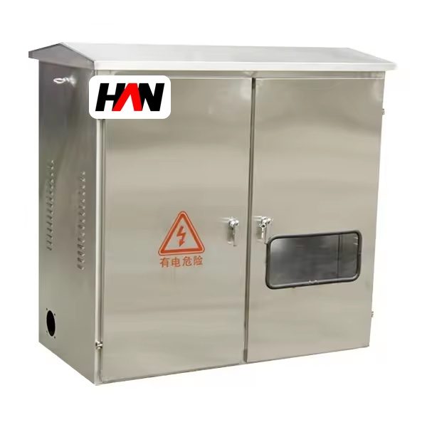
- Two enclosure families: painted steel to IP30 for a clean electrical room, and stainless steel to IP54 for the furnace platform or a dusty area, so the same internal layout serves both locations.
- Separate neutral and earth bars: every outgoing neutral has its own terminal and the earth bar is brought out to a dedicated stud, which keeps touch voltage under control and makes insulation testing a single operation.
- Built for maintenance: removable gland plates, a hinged door with a document pocket and a clear circuit schedule make a board that an electrician can restore before the next heat.
Selection and Commissioning
- Count circuits, not devices. List every final circuit with its load and its phase; the number of ways is that list plus the spares that the operation will inevitably add.
- Fix the incomer from upstream. The incomer rating has to sit below the rating of the cable and of the protective device that feeds the board, otherwise the board is the weakest link in the chain.
- Decide the residual current architecture. Group sensitive circuits together and keep lighting and instrument supplies on their own devices, so a trip does not remove the room’s light as well.
- Match the enclosure to the location. An electrical room takes IP30 painted steel; a platform or a dust-laden area takes IP54 stainless with a rain hood and a heater against condensation.
- Check the thermal margin. Confirm the number of devices that will be loaded at the same time, and derate the incomer when the board is fully populated inside a closed enclosure.
- Commission with three tests. Insulation resistance on every way, a trip test on each residual current device, and a thermographic scan after an hour at working load, which shows a loose terminal before it becomes a fault.
Frequently Asked Questions
Q1: Will a 30 mA device trip when a welding set is plugged into a socket circuit?
A: It can, because welding sets and portable tools carry leakage to earth through their own filters and through damp cables. The practical answer is a dedicated way for the welding socket with its own device, so a trip on that circuit does not take the platform lighting or the instrument supply with it.
Q2: Can a PZ30 board feed an air conditioner?
A: Yes, if the unit is single-phase and its running and starting current stay within the way rating and the incomer. For a three-phase unit, use a three-phase way with a four-pole device and size the incomer from the starting current rather than from the nameplate running current.
Q3: Can single-phase and three-phase circuits share the same board?
A: Yes, and in a melt shop they usually do. Keep the single-phase ways spread across the three phases, give each outgoing neutral its own terminal, and reserve the wider ways at the end of the rail for the three-phase devices that are added later.
Q4: What should be done when the inside of the box runs hot?
A: Measure first, then derate. Adding a larger breaker does not remove the heat, it only removes the protection. Space the devices, leave spare ways, fit filtered louvers to the IP54 version, and in a control room use a thermostat-controlled fan that draws air through the enclosure.
Plan the Final Circuits Early
Send the circuit list, the location of each board and the supply arrangement, and HANI Metallurgy will return a way schedule, an enclosure selection and a protection layout for your melt shop.