Description
Compact Substation
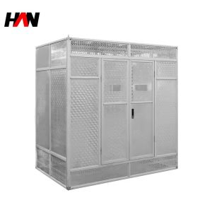
Walk-in transformer and switchgear room in one enclosure
Overview
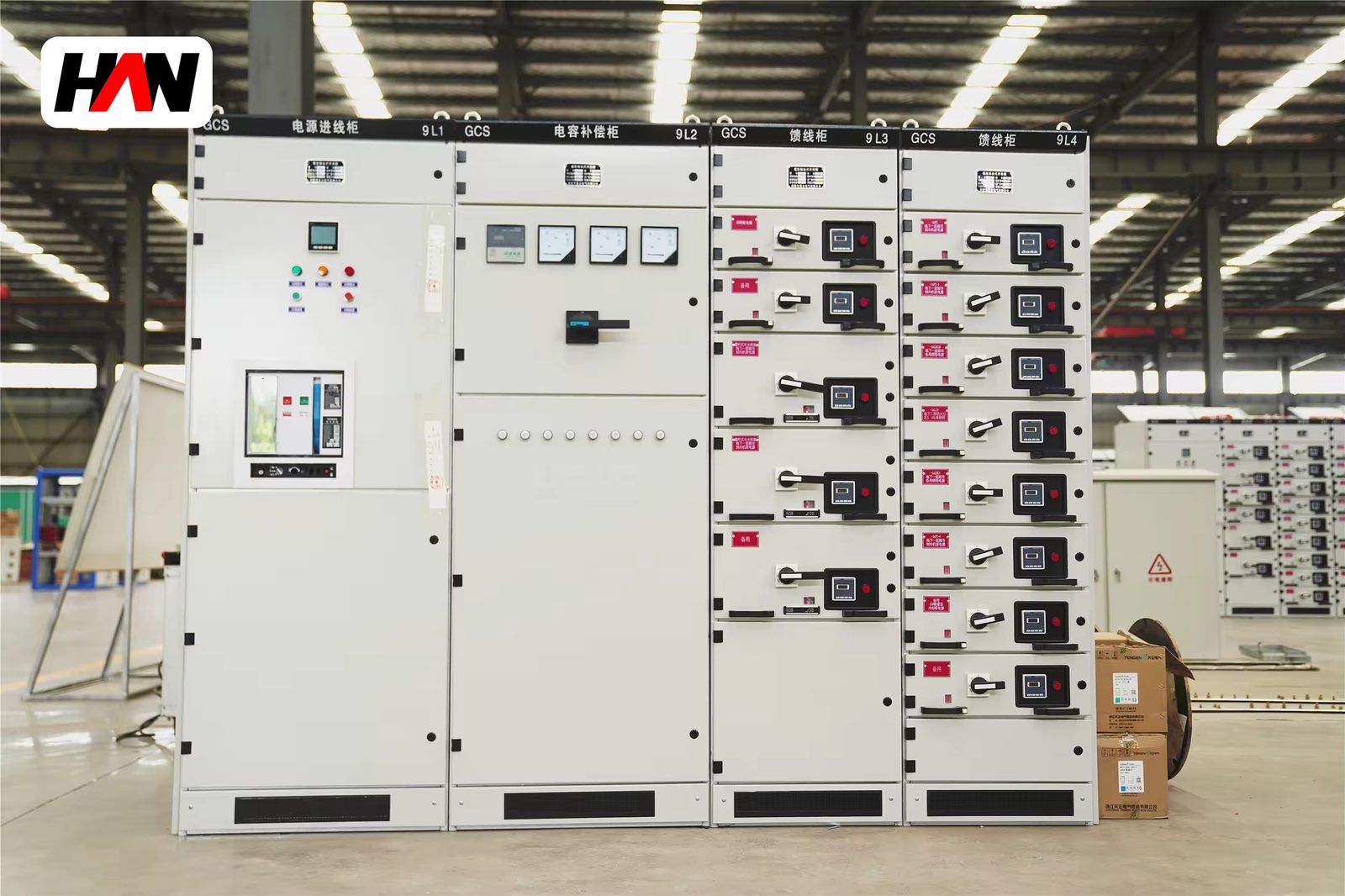
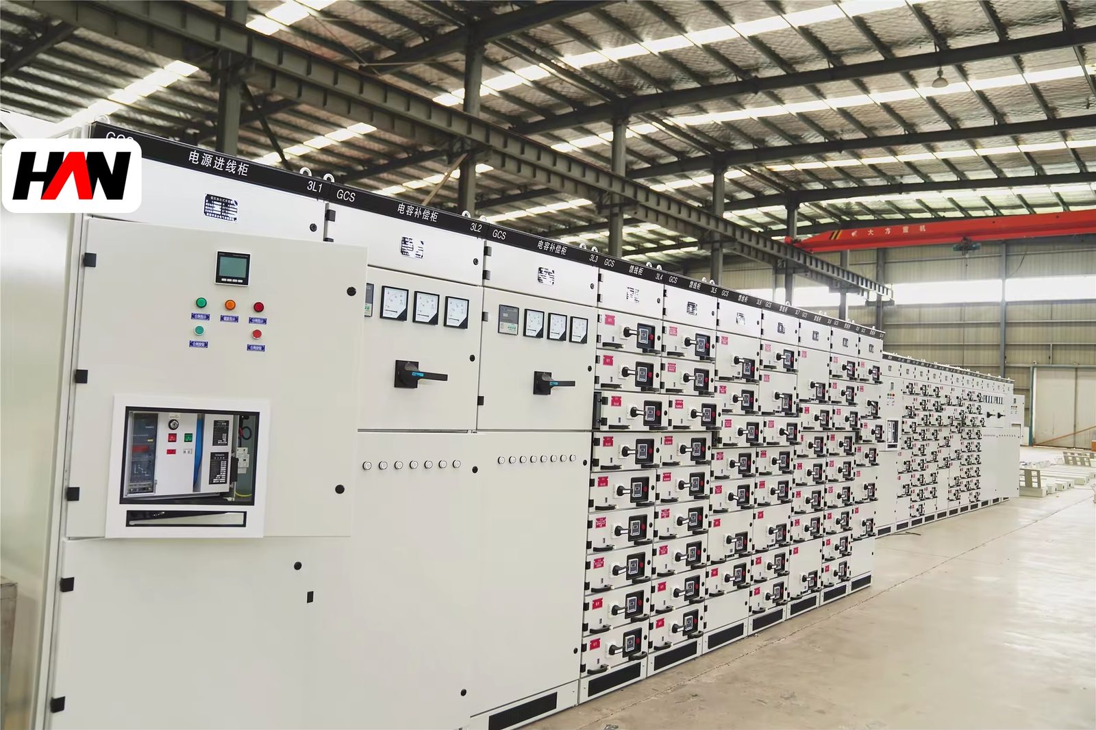
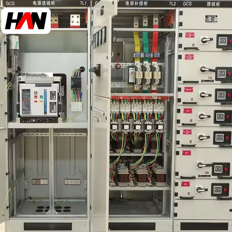
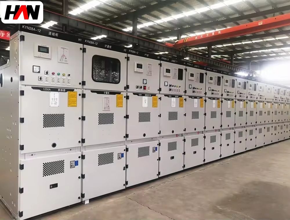
A compact substation is a factory-built enclosure that contains a medium-voltage room, a transformer room and a low-voltage room under one roof, with a walk-in corridor wide enough for a person to enter, inspect and work. It replaces a small brick-and-concrete distribution house at the edge of a melt shop with a steel structure that arrives assembled, is set on a prepared foundation and connected to the incoming cable and the outgoing feeders. HANI Metallurgy supplies compact substations for 6.6 kV, 10 kV and 35 kV systems with transformers up to 2500 kVA, built and type-tested to IEC 62271-202.
In a steel plant the unit usually serves the loads that surround the furnace rather than the furnace itself: the dedusting fans, the water treatment plant, the hydraulic station, the compressed air house, the workshop distribution and the offices. Placing the substation beside those loads shortens the low-voltage cable run, which is where a distribution system loses most of its energy and most of its voltage, and it removes the need to route a heavy low-voltage feeder across a yard that is already congested with duct banks and pipe racks. The trade-off is thermal: an enclosure with walls and roofs is a much hotter place for a transformer than an open yard, and the design of its ventilation decides whether the installed rating can actually be used.
Technical Parameters
| Parameter | Unit | 630 kVA | 1250 kVA | 2500 kVA |
|---|---|---|---|---|
| Transformer capacity | kVA | 630 | 1250 | 2500 |
| High-voltage supply | kV | 6.6 / 10 | 10 / 35 | 10 / 35 |
| Low-voltage output | V | 400 | 400 / 690 | 400 / 690 |
| Protection degree | IP | IP23D – IP54 | IP23D – IP54 | IP23D – IP54 |
| Compartment layout | — | HV room, transformer room, LV room, walk-in corridor | ||
| HV switchgear | — | ring main unit or metal-clad cubicles | ||
| Transformer cooling | — | ONAN | ONAN / ONAF | ONAF |
| Room ventilation | — | natural louver | louver + thermostat fan | louver + forced fan |
| Earthing | — | earth bar in every room, HV earthing switch, door bonding | ||
| Losses | — | within the limits of the transformer standard | ||
| Design standard | — | IEC 62271-202, IEC 61439 | ||
Typical values for reference. Final arrangement, protection degree and ventilation scheme are confirmed on the outline drawing and the approved project datasheet.
How It Works Under Furnace Duty
A compact substation is a heat engine as much as an electrical one. The transformer produces losses that leave the tank as heat, the low-voltage busbars and breakers produce more, and a metal enclosure with a roof traps that heat inside the rooms. IEC 62271-202 deals with this by defining a temperature-rise class and a verification method: the enclosure is tested with its ventilation arrangement in place, and the resulting rating is what may be installed, not the transformer’s open-air rating. In practice this means the ventilation scheme is chosen with the rating, not added afterwards. A 2500 kVA unit in a sealed room is not a 2500 kVA unit; it is a smaller unit with a hot transformer inside.
The layout follows the same logic. The high-voltage room is at one end, with the cable entry and the ring main unit or cubicles; the transformer room is in the middle, separated by a steel bulkhead with a fire-resistant rating; the low-voltage room is at the other end, with the outgoing feeders. Air enters through louvers at the low end of the transformer room, passes over the radiators and leaves through a high louver or an extract fan at the roof, so the path follows the natural rise of hot air rather than fighting it. Where the outgoing feeders are numerous, the low-voltage room is ventilated separately, because a room full of loaded breakers is a second heat source and should not share the transformer’s air.
For a melt shop the enclosure also has to survive its own environment. The unit sits beside a dedusting area or a scrap yard, so the louvers take in dust as well as air, and a filter that is never cleaned becomes a blockage that quietly derates the transformer. The practical answer is a louver with a removable filter frame, access from outside at standing height, and a maintenance note on the door. Doors are fitted with rain hoods, the roof is drained away from the walls, and the cable cellar is separated from the rooms so that water in the trench cannot reach the switchgear.
Engineering notes
1. IP23D is a rain-and-touch rating with a drip-proof roof; it is not a dust rating, and it relies on the louver being clear.
2. The walk-in corridor must be wide enough for a person with a tool bag and for the largest removable part of the switchgear, or maintenance becomes a removal job.
3. Bond the door, the gland plate and the transformer tank to the same earth bar; a floating door on an earthed enclosure is a touch-voltage hazard.
Key Advantages
- Three rooms, one footprint: high-voltage switchgear, transformer and low-voltage distribution are integrated in a single enclosure that is placed next to the load instead of behind a civil structure.
- Walk-in maintenance: a person can enter, inspect and operate the switchgear without dismantling the enclosure, which is the difference between a compact substation and a sealed pad-mounted unit.
- Ventilation matched to the rating: louver area, extract fan and radiator position are sized together with the transformer, so the installed rating stays valid inside the rooms.
- Fire separation between rooms: a steel bulkhead between the transformer room and the low-voltage room limits the spread of a fault and keeps the outgoing distribution available during transformer maintenance.
- Short low-voltage runs: placing the unit at the load keeps the 400 V feeder short, which is where voltage drop and cable cost both accumulate.
Selection and Commissioning
- Start from the load centre. Plot the large low-voltage loads on the plant layout; the substation goes where the cable metres are least, not where the space is easiest.
- Confirm the supply voltage and the fault level. The high-voltage equipment is selected for the system voltage and the prospective short-circuit current, not for the transformer rating alone.
- Fix the ventilation with the rating. Decide the louver area, the fan control and the radiator position before the enclosure drawing is frozen; ventilation added later rarely restores the full rating.
- Agree the foundation and cable entries. The plinth, the cable trench, the earthing grid connection and the drainage all have to be shown on the civil drawing before the unit is ordered.
- Check the transport route. Door widths, crane positions and the turning radius at the plant gate decide whether the unit arrives as one piece or in sections.
- Commission with a heat run. Log the room temperature and the transformer temperatures at full load for several hours, and confirm that the extract fan starts and stops at its set points.
Frequently Asked Questions
Q1: Does a compact substation need a concrete foundation?
A: Yes. It stands on a levelled concrete plinth with a cable trench and a connection to the plant earthing grid. The foundation is simpler than a civil building because it carries a steel structure rather than walls and a roof, but it still has to be designed for the weight and for the cable entries shown on the drawing.
Q2: How is the internal temperature controlled?
A: By a ventilation path that follows the heat: low louvers into the transformer room, air over the radiators, and a high louver or thermostat-controlled extract fan at the roof. In hot climates the fan is mandatory rather than optional, and the transformer is derated if the room temperature cannot be held within the design value.
Q3: Can two transformers be installed in one enclosure?
A: Yes, in a two-transformer arrangement with a separate transformer room for each unit and a common or split low-voltage board. The ventilation and the fire separation then have to be designed for two heat sources, and the enclosure footprint grows accordingly.
Q4: What does IP23D mean?
A: The first digit covers protection against fingers and against solid objects above a defined size, the second digit covers rain falling at an angle, and the letter D indicates a drip-proof design with drainage. It is the usual rating for a ventilated outdoor enclosure; it is not a dust-tight rating, and the louvers have to stay clear for it to mean anything.
Move the Substation to the Load
Send the plant layout, the load list, the supply voltage and the ambient conditions, and HANI Metallurgy will return a compartment arrangement, a ventilation scheme and a foundation outline.