Description
The Transformer of Ladle Refining Furnace
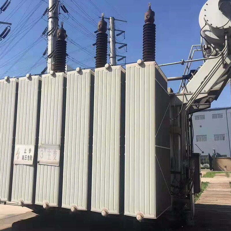
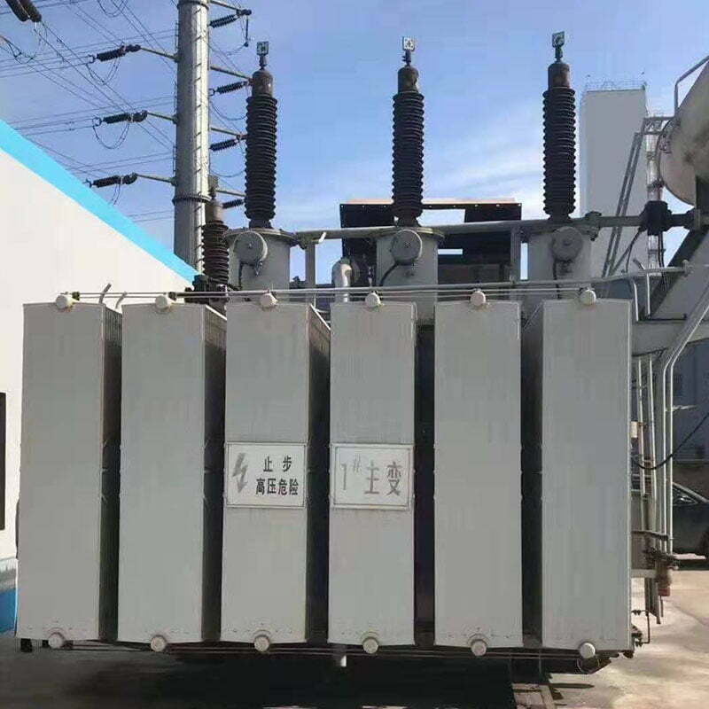
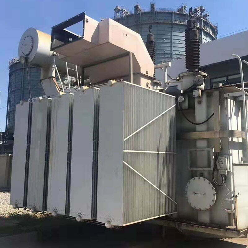
The transformer of the ladle refining furnace is a kind of electric furnace transformer with low output voltage, large current, fixed arc spike and small current fluctuation. In order to adapt to the change in furnace conditions, precision on-load voltage regulation is selected for all transformers.
The transformer is a kind of electrical equipment used to change AC voltage and current and transmit AC energy. It is based on the principle of electromagnetic induction to complete the transmission of electric energy. Transformers can be divided into power transformers, test transformers, instrument transformers, and transformers for special purposes: power transformers are necessary equipment for power transmission and distribution and power user distribution.
Parameters
| Model |
Rated Capacity (KVA)
|
Rated Voltage
|
Link group member
|
Weight(Kg)
|
Gauge(mm)
|
Outer size(mm)
|
|||
|
Primary Voltage(KV)
|
Secondary Voltage(V)
|
length×width×height
|
|||||||
|
HJSSP-2000/10
|
2000
|
10
|
185-150 4 level
|
Ddo
|
8000
|
1070
|
2100×1620×2590
|
||
|
HJSSP-2200/10
|
2200
|
10
|
180-150 4 level
|
Ddo
|
8300
|
1070
|
2350×1780×2600
|
||
|
HJSSP-2400/10
|
2400
|
10
|
200-190-180 6level
|
Yd11
|
9230
|
1070
|
2400×1670×2750
|
||
|
HJSSP-2500/20
|
2500
|
20
|
175-115 5 level
|
Yd11
|
8300
|
1070
|
2800×1600×2500
|
||
|
HJSSP-2800/10
|
2800
|
10
|
190-175-160 6level
|
Yd11
|
10300
|
1070
|
2800×1900×3300
|
||
|
HJSSP-3200/10
|
3200
|
10
|
180-110 5 level
|
Yd11
|
11000
|
1070
|
3260×1590×2700
|
||
|
HJSSP-4000/10
|
4000
|
10
|
210-155 4 level
|
Dd0
|
13450
|
1435
|
3000×2000×3500
|
||
|
HJSSP-5000/10
|
5000
|
10
|
212-195-155 5 level
|
Yd11
|
15000
|
1435
|
3200×2300×3100
|
||
|
HJSSP-5000/10
|
5000
|
10
|
210-195-180 6 level
|
Yd11
|
14500
|
1435
|
3200×1950×3400
|
||
|
HJSSP-5000/35
|
5000
|
35
|
215-196-155 5 level
|
Yd11
|
9100
|
1435
|
3800×2100×3150
|
||
|
HJSSP-5500/10
|
5500
|
10
|
230-212-145 6 level
|
Yd11
|
16000
|
1435
|
3200×2650×3550
|
||
|
HJSSP-5500/35
|
5500
|
35
|
210-121 6 level
|
Yd11
|
18900
|
1435
|
3800×2400×3350
|
||
|
HJSSP-5500/35
|
5500
|
35
|
212-195-155 lebel
|
Yd11
|
17850
|
1435
|
3700×2300×3800
|
||
|
HJSSP-6000/10
|
6000
|
10
|
230-206-145 6 level
|
Yd11
|
17000
|
1435
|
3760×1690×3280
|
||
|
HJSSP-6000/35
|
6000
|
35
|
220-182-145 6 level
|
Yd11
|
17500
|
1435
|
3810×1970×3170
|
||
|
HJSSP-6300/10
|
6300
|
10
|
364-313-262 6 level
|
Yd11
|
15600
|
1435
|
3564×2000×3000
|
||
|
HJSSP-6300/35
|
6300
|
35
|
225-200-151 6 level
|
Yd11
|
22000
|
1435
|
3750×2400×3750
|
||
|
HJSSP-6300/35
|
6300
|
35
|
215-155 5 level
|
Yd11
|
19000
|
1435
|
3700×2300×4500
|
||
|
HJSSP-6300/35
|
6300
|
35
|
240-190-160 6 level
|
Yd11
|
22000
|
1435
|
3990×4160×3920
|
||
|
HJSSPZ-7000/10
|
7000
|
10
|
200-135 7 level
|
Yd11
|
21500
|
1435
|
4120×2200×3000
|
||
|
HJSSP-7000/10
|
7000
|
10
|
216-161 5 level
|
Ddo
|
17500
|
1435
|
3600×2200×3600
|
||
|
HJSSP-7000/35
|
7000
|
35
|
220-145 6 level
|
Yd11
|
21600
|
1435
|
4350×2400×4500
|
||
|
HJSSPZ-7000/35
|
7000
|
35
|
225-188-151 6 level
|
Yd11
|
22000
|
1435
|
3590×2410×3680
|
||
|
HJSSPZ-7000/35
|
7000
|
35
|
250-204-130 6 level
|
Yd11
|
27000
|
1435
|
3855×2800×3980
|
||
|
HJSSP-8000/35
|
8000
|
35
|
240-155 6 level
|
Yd11
|
22000
|
1435
|
4200×2600×4600
|
||
|
HJSSPZ-8000/35
|
8000
|
35
|
270-250-170 9 level
|
Yd11
|
29500
|
1435
|
4600×2400×4000
|
||
|
HJSSPZ-8500/35
|
8500
|
35
|
240-220-155 6 level
|
Yd11
|
27500
|
1435
|
4500×2500×3700
|
||
|
HJSSP-9000/35
|
9000
|
35
|
240-223-165 13 level
|
Yd11
|
21500
|
1435
|
4120×2450×4100
|
||
|
HJSSPZ-9000/35
|
9000
|
35
|
240-224-195 9 level
|
Yd11
|
27500
|
1435
|
4400×2500×4100
|
||
|
HJSSP-10000/10
|
10000
|
10
|
240-170 9 level
|
Ddo
|
21000
|
1435
|
3800×2420×3900
|
||
|
HJSSPZ-10000/35
|
10000
|
35
|
260-240-160 9 level
|
Yd11
|
28000
|
1435
|
4400×2500×4400
|
||
|
HJSSPZ-12000/35
|
12000
|
35
|
270-250-165 9 level
|
Yd11
|
31500
|
1435
|
4500×2600×4300
|
||
|
HJSSP-12000/35
|
12000
|
35
|
270-250-170 9 level
|
Yd11
|
31000
|
1435
|
4600×2400×4300
|
||
|
HJSSPZ-12500/10
|
12500
|
10
|
270-225-150 15 level
|
Ddo
|
27500
|
1435
|
4520×2800×4700
|
||
|
HJSSPZ-12500/35
|
12500
|
35
|
270-250-170 9 level
|
Yd11
|
31700
|
1435
|
4500×2600×4400
|
||
|
HJSSPZ-12500/35
|
12500
|
35
|
270-250-170 9 level
|
Yd11
|
29000
|
1435
|
3900×2400×3850
|
||
|
HJSSPZ-13000/35
|
13000
|
35
|
240-220-120 9 level
|
Yd11
|
36000
|
1435
|
4100×3000×4050
|
||
|
HJSSPZ-14000/35
|
14000
|
35
|
290-260-210 9 level
|
Yd11
|
31900
|
1435
|
4520×3200×4700
|
||
|
HJSSPZ-14000/35
|
14000
|
35
|
300-267-190 11 level
|
Yd11
|
41200
|
1435
|
4000×3300×4200
|
||
|
HJSSPZ-15000/35
|
15000
|
35
|
370-270-170 13 level
|
Yd11
|
49500
|
1435
|
4200×4100×4500
|
||
|
HJSSPZ-15000/35
|
15000
|
35
|
300-240-150 11 level
|
Yd11
|
37500
|
1435
|
4300×3350×4800
|
||
|
HJSSPZ-15000/35
|
15000
|
35
|
315-285-165 13 level
|
Yd11
|
35400
|
1435
|
4700×2600×4700
|
||
|
HJSSPZ-17000/35
|
17000
|
35
|
330-270-170 9 level
|
Yd11
|
48500
|
1435
|
4600×3300×4200
|
||
|
HJSSPZ-18000/35
|
18000
|
35
|
345-312-235 11 level
|
Yd11
|
42700
|
1435
|
4300×3520×5000
|
||
|
HJSSPZ-20000/35
|
20000
|
35
|
350-309-228 13 level
|
Yd11
|
39500
|
1435
|
4800×2700×4700
|
||
|
HJSSPZ-21000/35
|
21000
|
35
|
340-310-240 11 level
|
Yd11
|
43500
|
1435
|
5200×3100×4500
|
||
|
HJSSPZ-22000/35
|
22000
|
35
|
370-319-200 11 level
|
Yd11
|
48500
|
1435
|
4700×3300×4500
|
||
|
HJSSPZ-23000/35
|
23000
|
35
|
350-315-191 13 level
|
Yd11
|
47850
|
1435
|
4600×3200×4600
|
||
|
HJSSPZ-24000/35
|
24000
|
35
|
395-345-190 17 level
|
Yd11
|
43800
|
1435
|
4900×2800×4800
|
||
|
HJSSPZ-25000/35
|
25000
|
35
|
400-325-160 17 level
|
Yd11
|
51400
|
1435
|
4700×4200×5000
|
||
|
HJSSPZ-26000/35
|
26000
|
35
|
400-360-220 17 level
|
Yd11
|
52000
|
1435
|
4750×3920×5150
|
||
|
HJSSPZ-26000/35
|
26000
|
35
|
420-384-276 13 level
|
Yd11
|
55000
|
1435
|
4400×3200×5100
|
||
|
HJSSPZ-28000/35
|
28000
|
35
|
420-340-260 19 level
|
Yd11
|
56000
|
1435
|
5200×3100×5250
|
||
|
HJSSPZ-28000/35
|
28000
|
35
|
425-395-305 13 level
|
Yd11
|
57000
|
1435
|
4300×3500×5150
|
||
|
HJSSPZ-30000/35
|
30000
|
35
|
480-400-240 19 level
|
Yd11
|
65000
|
2000
|
4850×3700×5600
|
||
|
HJSSPZ-35000/35
|
35000
|
35
|
380-355-230 13 level
|
Yd11
|
71000
|
2000
|
4600×3700×5200
|
||
|
HJSSPZ-38000/35
|
38000
|
35
|
480-405-300 19 level
|
Yd11
|
74500
|
2000
|
5100×5350×5700
|
||
|
HJSSPZ-44000/35
|
44000
|
35
|
486-464-366 19 level
|
Yd11
|
78000
|
2000
|
6450×4650×5500
|
||
Features
1. The transformer itself has good energy-saving characteristics: no-load loss, no-load current and load loss. Reduce the percentage of impedance voltage as much as possible, select the appropriate capacity in common use, make use of existing high-quality raw materials and small oil gap and other advanced technologies, so as to make the transformer truly energy-saving, and the performance level is consistent with the products of international developed countries.
2. The transformer of the ladle refining furnace has very stable reliability and long service life. The product design technology of the new structure shall be verified by operation tests and type tests, and the design life shall not be less than 30 years.
3. A certain overload capacity is required to ensure the proper operation of various operation indicators under the condition of exceeding the weighing capacity and 20% load.
4. Reduce the maintenance workload of the user, so that the user will no longer hang the core in long-term use, and the design is free of charge. The maintenance time shall not be less than ten years. The overhaul free time is 20 years.
5. Selection of transformer material, structure and process: the following is divided into six parts as a brief introduction. Namely: iron core, winding, body, oil tank, general assembly and accessories. The following are introduced respectively
5.1 Iron core: in terms of materials, we selected a 30q130 silicon steel sheet produced by WISCO or a 30z130 silicon steel sheet produced by Nippon Steel Co., Ltd. of Japan. These materials are basically consistent with those used in internationally developed countries.
The structure adopts the full inclined seam sheet type, and the upper and lower clamps are connected with the pull plate structure of a low-magnetic steel plate, which changes the previous square iron structure, so that there are no holes and defects on the iron chip, the magnetic flux density of each section of the iron core is consistent and there is no distortion. In the shear process, the Jorge shear line imported from Germany is adopted, and the shear burr is controlled to be less than 0.02mm (the standard < 0.05 is the qualified product), and the length tolerance per meter is less than 0.2mm, so as to increase the lamination coefficient and reduce the butt joint gap, The local overheating of the iron core is avoided, and the product noise, no-load loss and no-load current are reduced.
5.2 Winding: use oxygen-free copper electromagnetic wire from the material to control its ρ 20 ℃ < 0.017241. In addition, the material and tightness of paper package insulation shall be controlled. The purpose is to make the coil have better axial and radial stability as far as possible. The coil adopts a small oil gap, internal and external oil baffle, guiding cooling and hard paper cylinder structure, so as to make the structure compact, and improve the overload capacity and thermal stability. Losses have also decreased.
5.3 Body: all wood parts of the body are changed into laminated wood, which improves the stiffness of the lead frame. The upper and lower pressing plates are made of paperboard or epoxy resin. Compared with the iron pressing plate, it increases the insulation distance between the electrical conductor and the ground and reduces the size of the “window height”. 1、 The secondary main insulation adopts imported paperboard, which increases the strength of the main insulation. The multi-coil adopts an integral suit, which improves the reliability of the product. The steam phase drying equipment produced in Norway is used for the drying of the body, which is completely dry without damaging the insulation and has the function of flushing the body.
5.4 Oil tank: the oil tank adopts the folded plate type, reduces the welds as much as possible, increases the strength, and makes positive and negative pressure tests to ensure the reliability of product sealing. A low magnetic steel plate or magnetic shield shall be used at appropriate parts to reduce the additional loss caused by the magnetic field of bus conductor on the tank wall. This work has achieved very good results in seepage prevention and loss reduction.
5.5 Final assembly: after the body is dry, the winding is loose and compressed by hydraulic equipment, which has achieved good results. Vacuum oil injection is adopted to reduce bubbles in the product winding, reduce partial discharge and increase the service life of the product. The use of anti-aging new sealing material improves the original leakage problem.
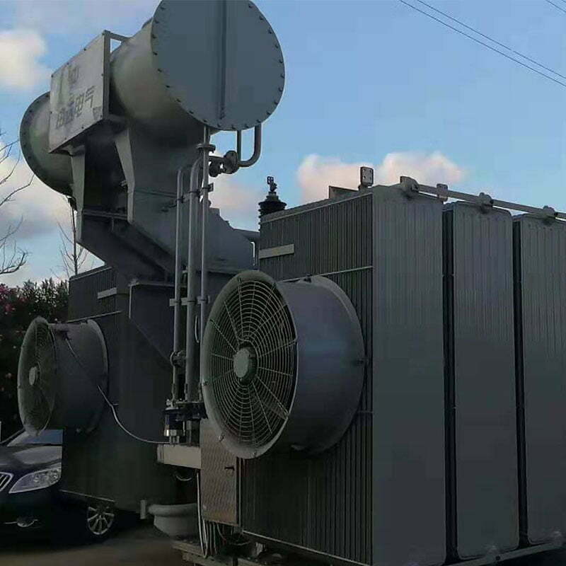
5.6 Accessories: the main accessory water cooler shall be a tubular or spiral plate oil-water cooler, or installed separately or directly fixed on the transformer host.
The on-load tap changer shall be imported from ABB company, MR company, or Changzheng No. 1 plant. In addition to a remote display, it also has a remote control interface.
Transformer oil is made from naphthenic aging transformer oil in Karamay. The protection of oil is a fully closed structure (that is, a pressure relief valve with a diaphragm storage tank structure).
6. About transformer maintenance
It is necessary to transport the hanging core after the arrival of the product as long-distance transportation, which mainly involves the loosening of fasteners during transportation and the user’s acceptance of the manufacturer’s products. However, as for the routine overhaul, we think it is necessary to check and replace those mechanical wear parts according to the original overhaul cycle. Such as pumps and other running parts, but for the relatively static transformer, it is not necessary to hang the core for a long time. Only monitoring the quality changes of oil, such as gas chromatography, is enough to grasp the situation of the body, so as to save the maintenance cost and reduce the pollution of the hanging core to the body and oil.
7. Product quality assurance measures
7.1 Ensure long-term overload of 20%. For example, if the transformer for LF furnace has a capacity of 20000kva, the design basis capacity of the winding shall be set to 24000kva, especially the current density and switch selection shall be selected according to 24000kva, and the impedance voltage shall not be greater than 8% at 24000kva. With good external characteristics and economy, the thermal load calculation of the transformer is set at 24000kva, and the lead, secondary outlet, cooler and other load related accessories are selected under the condition that 24000kva has a certain margin.
7.2 Technical measures for impact resistance and short circuit resistance: due to the long production time of the electric furnace transformers, especially the impact state of the electric arc steelmaking furnaces is worse than that of the LF furnaces. The main technical measures adopted by our company are to improve the axial and radial stability of the transformer coil, so as to reduce the accumulation of damage to the transformer coil caused by each impact. Specific measures:
a. Select the electromagnetic wire with a higher voltage level and tightly wrapped paper and surface treatment.
b. After the electromagnetic wire is purchased, it shall be dried first and then wound to prevent the damp insulation paper of the coil, which will affect the amplitude winding tightness of the coil.
c. The cushion block is used after densification to reduce the axial pressure margin of the coil.
d. Depilation treatment of the brace to reduce the friction between the brace and the “dovetail” of the cushion block, so that the force transmission resistance of the coil is small when the coil is pressed axially.
e. Coil drying adopts constant pressure drying.
f. The inner coil adopts multiple support bars and the outer coil adopts external support bars to ensure that the displacement of the wire cake is small during short-circuit impact.
g. The body adopts vapor phase drying.
h. Hydraulic device is used for pressing the body.
7.3 Technical measures to ensure no overhaul within 20 years of operation. Our company’s main products are mainly the stability and reliability of transformer windings. This has been explained, followed by the aging of transformer oil and the aging seals. For the transformer oil, we choose naphthenic base oil from Karamay, Xinjiang, which has a strong anti-aging ability. With a closed structure, a diaphragm oil storage tank with a pressure relief valve, so that oil does not contact with air, so the oil in normal operation can be used for 20 years. Besides anti-aging mats, the main sealing surfaces should be machined and treated, so that the three sides of the pad and metal will be compressed, and the contact with air will be reduced. In addition, the users are required to perform an oil spectrum analysis every 6 months and file in order to distinguish the normal aging of the oil from the failure operation and ensure that the products used are at ease. The transformer’s load switch suggests that the oil breakdown voltage should be made in the switching switch according to the number of operations. The value should be consistent with the switch, and then in the design, consider that all fasteners of the body adopt butterfly washers to prevent looseness, so as to strengthen the reliability of locking.
7.4 Appearance features: in the design, the product structure is compact. Various transformer control lines are connected to a unified junction box and the purpose is explained to make it beautiful and easy to operate.
Customized Transformer of Ladle Refining Furnace
We can design and manufacture the transformer of the ladle refining furnace according to the client’s required capacity, working hours, power supply, raw materials, and other related parameters. It can also be matched for users who already have the transformer of the ladle refining furnace.
Custom Range
Rated capacity: 2,000-44,000 KVA
Primary Voltage: 10-35 KV
Secondary Voltage: 185-486V
Weight: 8,000-78,000 kg
Service
We can provide foundation layout and layout drawings
We will send engineers to your factory to install and debug machines and provide reliable after-sales service.
Competitive price and excellent quality
Our machines are easy to operate and maintain
Less investment
Stable performance
Products can be customized according to different need
Production capacity can be adjusted according to customer requirements
Low energy consumption

