Description
SF6 Ring Main Unit
Compact ring switching for plant auxiliary networks
Overview
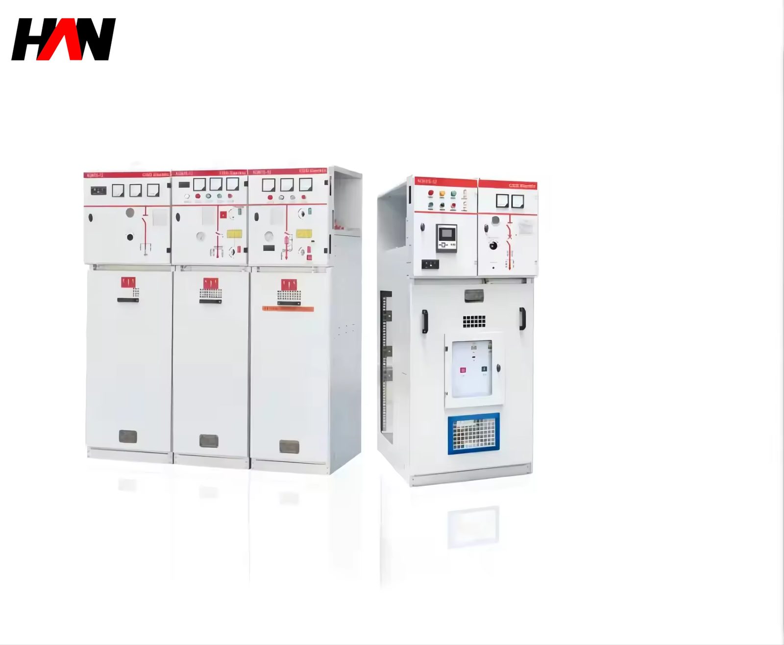
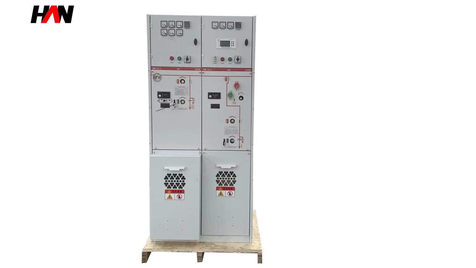
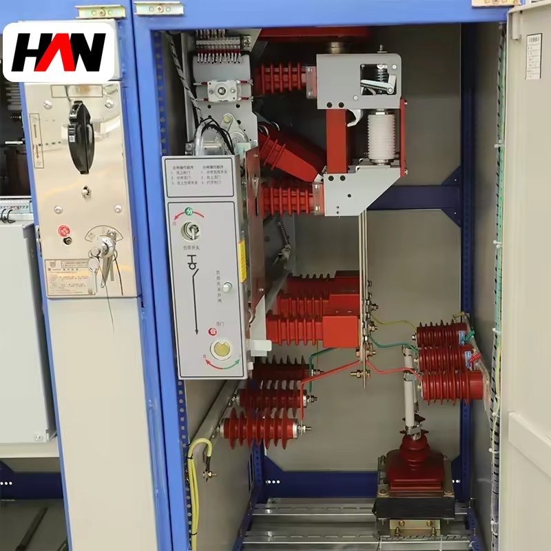
An SF6 ring main unit is a factory-built switching assembly in which the busbar, the load-break switches, the earthing switches and, where required, a fuse-protected transformer tee are enclosed in a sealed gas tank. It is the node that turns a radial cable run into a ring: two ways come in from the upstream substation, two ways continue the loop, and one or two tees feed the transformers that actually carry the load. Rated voltage covers 12 kV, 24 kV and 40.5 kV, the rated current is 630 A throughout, and the short-time withstand is 20 to 25 kA for 3 to 4 s. That window matches the auxiliary distribution level of a steel plant: enough to switch a workshop transformer or a dedusting substation, small enough to stand beside a cable trench.
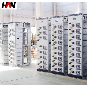
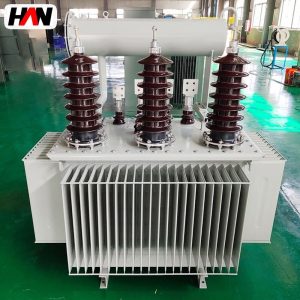
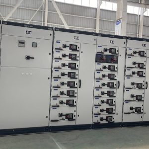
In a melt shop the auxiliary network is long and spread out. Dedusting fans sit at the bag house, water recirculation pumps at the cooling tower, conveyor and charging systems along the bay, and each of them is fed by a small transformer of its own. Building a switchgear room at every one of those points is expensive, and it puts a large volume of live busbar into a dusty area. The ring main unit replaces that room with a sealed tank, a cable compartment and a mimic panel. HANI Metallurgy supplies these units as part of the auxiliary distribution package around an electric arc furnace, together with the downstream low-voltage boards and the motor control centres they feed.
Technical Parameters
| Parameter | Unit | 12 kV | 24 kV | 40.5 kV |
|---|---|---|---|---|
| Rated voltage | kV | 12 | 24 | 40.5 |
| Rated current, busbar and tee | A | 630 | 630 | 630 |
| Short-time withstand current | kA / 3-4 s | 20 | 25 | 25 |
| Peak withstand current | kA | 50 | 63 | 63 |
| Lightning impulse withstand | kV | 75 | 125 | 185 |
| Ways per unit | — | 2 to 4, ring or ring plus tee | ||
| Switch type | — | Three-position, close / open / earth | ||
| Transformer tee protection | — | Switch-fuse combination, striker tripping | ||
| Protection of the gas tank | — | IP67, welded stainless steel | ||
| Gas monitoring | — | Density monitor with alarm and lockout contacts | ||
| Design standard | — | IEC 62271-200 / IEC 62271-103 | ||
Typical values for reference. Final ratings, way configuration and fuse selection are fixed on the nameplate and the approved project datasheet.
How It Works Under Furnace Duty
The heart of the unit is the three-position switch. One operating shaft moves the moving contact through three fixed positions: closed to the busbar, open in the middle, and closed to earth. The three positions cannot be skipped and cannot be held between them. Around that shaft sits a mechanical interlock chain: the earthing switch cannot be closed while the load switch is closed, the cable compartment cover cannot be opened until the earth switch is closed, and each way is keyed so that a node with two incomers can only be worked from one side at a time. The interlocks are mechanical and built into the tank, so a wrong sequence is not a control logic question, it is physically impossible.
Arcing takes place inside sulphur hexafluoride at slight overpressure, in a welded stainless tank sealed for life and rated IP67. The gas recovers its dielectric strength after each interruption, so the switch clears the magnetising current of a distribution transformer and the rated load current of the ring without contact maintenance. A density monitor watches pressure and temperature together and gives an alarm at the first stage and a lockout at the second. Because the tank is never opened in service, dust, metal fines and humidity never reach the contacts. A switchgear room next to a bag house will always be dusty, and the sealed tank removes the problem instead of filtering it.
The transformer tee is a switch-fuse combination. A striker pin on the fuse trips the load-break switch when a fuse element operates, which turns a single-phase fuse failure into a three-phase trip and prevents single-phasing the transformer. The fuse is chosen against the transformer’s inrush so that energising current does not blow it, and against its secondary fault current so that a terminal short is cleared before the transformer is damaged. In the ring itself, the two incoming ways are normally both closed. A cable fault is isolated by opening the two ways on either side of it, and every other node on the loop stays energised.
Engineering notes
1. The gas tank is sealed for life; the cable compartment is not. The compartment needs a heater, a drain and a gland plate that is sealed after termination.
2. Rated current of the tee is set by the fuse holder, not by the busbar. A 630 A busbar can carry a much smaller tee and that is normal.
3. The earth switch is a fault-making device on the cable side only. It is rated for the peak current of the ring, not for a back-feed from the plant.
Key Advantages
- No switchgear room required: four ways, a cable compartment and the operating interface fit in a single enclosure that can stand at the end of a trench or inside a small kiosk, which removes a civil works package from the auxiliary network.
- Contacts sealed against plant dust: the live parts never see the atmosphere of the melt shop, so contact resistance and flashover risk do not drift with the cleanliness of the building.
- Interlocks that cannot be bypassed: the close, open and earth sequence is enforced mechanically inside the tank, which is what makes the unit safe to operate by a shifting electrician rather than a specialist.
- Fast fault isolation on the ring: a damaged cable section is switched out at both ends while the rest of the loop keeps supplying the dedusting, water and workshop transformers.
- Simple protection for small transformers: a switch-fuse tee clears a transformer fault without a relay, a battery and a trip circuit.
Selection and Commissioning
- Draw the ring first. Way count, cable sizes, the direction of each feeder and the position of every tee are decided on the single-line diagram before the enclosure is chosen.
- Confirm the fault level at the node. The short-time withstand and the peak withstand must both cover the upstream contribution; a 12 kV node fed from a large transformer is not the same as one at the end of a long cable.
- Select the tee protection. Switch-fuse for small auxiliary transformers, a vacuum breaker way where settings, remote control or frequent switching are needed.
- Check the cable space. Termination room and bending radius of the incoming cable decide the enclosure depth, and that is expensive to change later.
- Treat the environment explicitly. Specify the heater, the kiosk or shelter, and the cable entry sealing for the dust and condensation level of the site.
- Commission in sequence. Gas density check, power-frequency test on the cable side, five operations of each way, phase identification and a trip test of every fuse striker before the ring is closed.
Frequently Asked Questions
Q1: Can a ring main unit include a circuit breaker instead of a switch-fuse?
A: Yes. Vacuum breaker ways are available in the same family for feeders that need overcurrent settings, remote operation or frequent switching. For a small auxiliary transformer the switch-fuse is usually the better answer, because the fuse clears a transformer fault faster than a relay and needs no auxiliary supply.
Q2: Does the SF6 tank need periodic gas topping up?
A: The tank is sealed for life and is not a maintenance item. A density monitor compensates for temperature and gives an alarm, then a lockout, if pressure falls. If the alarm appears, the unit is de-energised and the leak is located and repaired.
Q3: How does the unit divide work with metal-clad switchgear?
A: By function. Metal-clad switchgear sits at the main substation, where breaking capacity, protection settings, metering and testing need full compartmentation. The ring main unit sits downstream at the loop nodes, where the job is switching and fault isolation.
Q4: Can it be installed outdoors?
A: The gas tank itself is IP67, but the cable compartment and the operating mechanism are not. Outdoors the unit goes into a kiosk or shelter with a rain hood, a heater and sealed cable entries, and the same arrangement is used indoors where dust and condensation are heavy.
Build the Ring Around the Melt Shop
Send the single-line diagram, the fault level and the auxiliary transformer list, and HANI Metallurgy will return a way configuration, a fuse schedule and an outline drawing.