Description
XL-21 Distribution Cabinet
Local power distribution for furnace auxiliaries
Overview
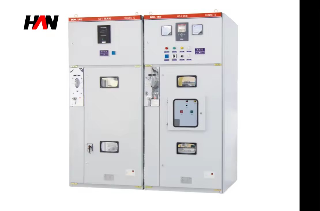
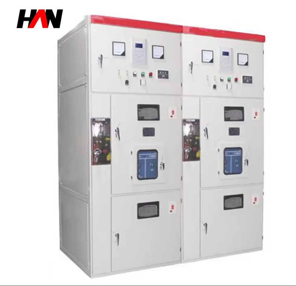
An XL-21 distribution cabinet is a floor-standing, single-door low-voltage cabinet that takes one incoming feeder and splits it into a small number of outgoing circuits. It is the layer between a motor control centre or a main low-voltage board and the individual loads scattered around a melt shop: lighting circuits on the charging floor, maintenance sockets at the furnace platform, solenoid valves on the hydraulic unit, small fans and pumps in the dedusting area, and the local supplies for welding and tools during a repair.
The ratings are modest by plant standards, from 100 A to 630 A at 400 V or 230 V, with a short-time withstand of 15 to 30 kA, built to IEC 61439-2 and IEC 61439-3. The value of the product is not in the numbers but in the physical arrangement: a single door that gives access to the incoming terminals and the outgoing breakers, a cable entry that matches how the site actually pulls cable, and an enclosure that keeps conducting dust off the busbars in a building where dust is a permanent condition. HANI Metallurgy builds these cabinets as the last distribution step before the load, matched to the same protection philosophy as the upstream board.
Technical Parameters
| Parameter | Unit | 160 A | 400 A | 630 A |
|---|---|---|---|---|
| Rated current | A | 160 | 400 | 630 |
| Rated voltage | V | 400 / 230 | 400 / 230 | 400 / 230 |
| Short-time withstand | kA | 15 | 25 | 30 |
| Outgoing ways | ways | 6 – 8 | 8 – 10 | 10 – 12 |
| Protection degree | — | IP30 – IP54 | IP30 – IP54 | IP30 – IP54 |
| Form of construction | — | floor-standing, single front door, fixed devices | ||
| Cable entry | — | top or bottom, removable gland plates | ||
| Busbar | — | copper, insulated supports, phase-labelled | ||
| Residual current protection | — | outgoing RCD optional, 30 mA for socket circuits | ||
| Enclosure dimensions | — | fixed by way count and cable space, confirmed on drawing | ||
| Design standard | — | IEC 61439-2 / IEC 61439-3 | ||
Typical values for reference. Final ratings, way count and enclosure dimensions are confirmed on the nameplate and the approved project datasheet.
How It Works Under Furnace Duty
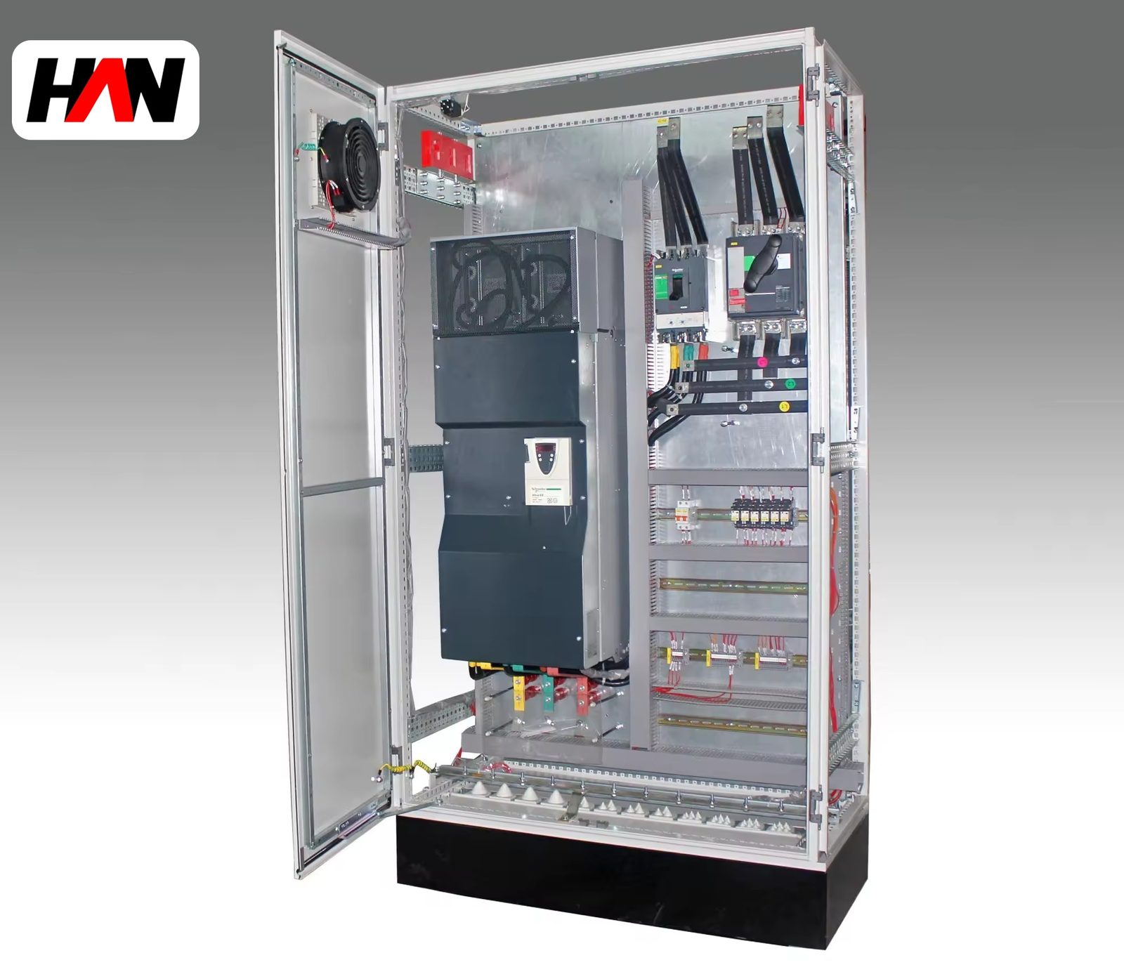
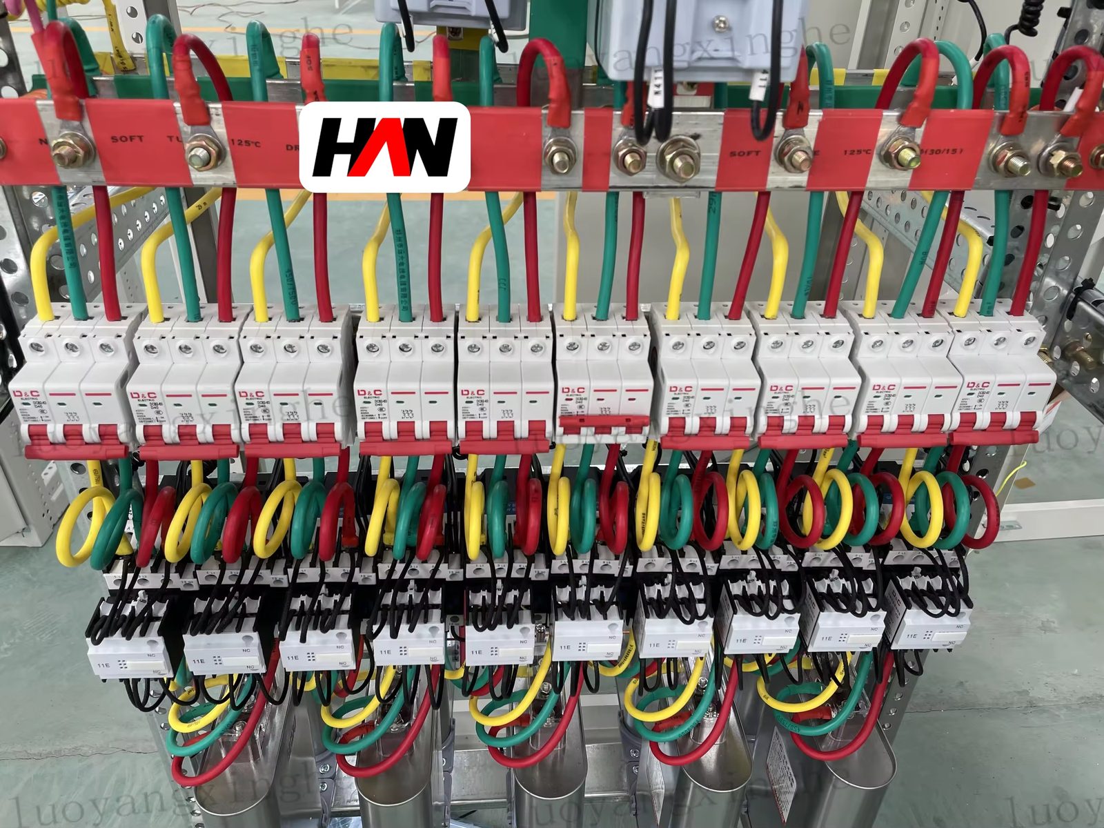
The cabinet has one incoming device, a set of copper busbars and a row of outgoing breakers or fuse-switch units. That is the whole electrical content, and because it is simple it is also the part of the distribution chain that is most often installed badly. The busbar is mounted on insulated supports with phase labels, the incoming cable lands on a set of terminals sized for the lug, and the outgoing cables leave through gland plates at the top or the bottom. Where the cabinet is fed from above, the cable compartment must be tall enough for the bends; where it is fed from below, the gland plate must be removable so the cable can be dressed before it is bolted to the terminal.
Temperature rise is the limit that decides the real rating. A fixed-device cabinet with a single door has no internal partitions and no forced airflow, so the heat from the breakers, the busbar joints and the cable lugs accumulates in the upper part of the enclosure. The standard rating assumes an ambient of the reference value, and a melt shop corridor at 45 °C is above it; the outgoing devices are therefore selected with a derating factor, and a cabinet loaded to its nominal current in a hot corridor will run its terminals near the limit. The practical rule is to leave spare ways and to keep the top of the cabinet clear so that the warm air can leave through the louvres.
Short-circuit withstand is the second limit. The 15 to 30 kA rating applies to the busbar and the incoming terminals, and it is only valid if the outgoing devices are chosen with a prospective fault level that matches the board they are fed from. A cabinet with a 25 kA busbar and breakers rated at 10 kA gives a false sense of protection: the busbar survives, the breaker does not, and the fault is cleared by the upstream device after the local one has failed. Dust is the third issue, and in a melt shop it is the one that actually causes failures. Conductive dust bridging a busbar support produces a phase-to-phase fault at a current the upstream protection may not see quickly; the cabinet is therefore specified with IP54 gaskets in dusty areas.
Engineering notes
1. Keep two spare ways on every cabinet; the cost is small and the alternative is a new cabinet for one additional fan.
2. Match the outgoing device rating to the prospective fault current at the cabinet, not to the current of the load.
3. RCD protection on socket and maintenance circuits is a personnel measure, so it is set at 30 mA and is never shared with a process load.
Key Advantages
- Simple enough to maintain in the shop: one door, visible busbars and fixed devices, so a fitter can find a blown circuit and restore it without a drawing or a specialist.
- Cable entry that matches site practice: removable gland plates at the top and the bottom, with space for the bend radius of the cables actually used rather than for the catalogue.
- Dust protection option: gasketed IP54 construction for the dusty corridors and the furnace platform, where an open IP30 panel would collect conductive dust within a month.
- Personnel protection on maintenance circuits: 30 mA residual current devices on socket outlets and local supplies, kept separate from process feeders so a trip does not stop a pump.
- Clear place in the hierarchy: it is a distribution cabinet, not a motor control centre, and it is specified with that boundary in mind so that the MCC keeps the motor protection and the interlocks.
Selection and Commissioning
- List the loads before the ways. Lighting, sockets, valves, small fans and welding supplies are counted with their diversity, and the incoming device is sized from that total rather than from the sum of the breakers.
- Check the fault level at the cabinet. The further the cabinet is from the main board, the lower the prospective current; the outgoing devices are chosen for the value at that point.
- Decide the entry before fabrication. Top entry from a tray and bottom entry from a trench need different plates and different internal space, and the decision is frozen on the outline drawing.
- Reserve the spare ways. Two spare ways per cabinet, with the busbar extended to them, avoid a new cabinet when a fan or a valve is added later.
- Bond the enclosure and the door. The door is bonded to the frame with a flexible conductor, and the frame is connected to the plant earth before the incoming cable is terminated.
- Test before energizing. Insulation resistance, RCD trip test on every residual current device, and a thermal scan of the terminals under load on the first day.
Frequently Asked Questions
Q1: How large a motor can an XL-21 cabinet feed?
A: It can feed a motor within its 100 to 630 A range, but it does not provide motor protection or control. A motor of any size that needs overload protection, start/stop control and interlocks belongs in a motor control centre; the cabinet is for distribution, lighting, valves and small auxiliary supplies.
Q2: What is the difference between this cabinet and a final distribution board?
A: Current rating, construction and location. The cabinet is a floor-standing metal enclosure for power circuits up to 630 A, installed in a workshop or a corridor. A final board is a smaller enclosure for terminal circuits such as lighting and sockets, mounted on a wall inside a room.
Q3: Can it be installed outdoors?
A: The standard cabinet is for indoor use. An outdoor installation needs a canopy, a raised plinth, gasketed IP54 or better construction and a drainage path; at that point a purpose-built outdoor box is usually the better choice, because the door seal and the cable entry are designed for weather from the start.
Q4: Is residual current protection required?
A: It is required for socket outlets and maintenance supplies, where the risk is a person touching a live part, and it is normally 30 mA. For process feeders a residual current device is a design decision based on the earth fault protection scheme, because nuisance tripping on a dusty or damp circuit costs production.
Complete the Last Step of Distribution
Send the load list, the fault level at the installation point and the cable entry arrangement, and HANI Metallurgy will return a cabinet layout with the ways, the protection and the enclosure degree fixed.