Description
Prefabricated Substation for EAF Projects
Transformer, MV switchgear and LV distribution on one skid
Overview
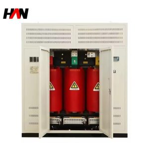
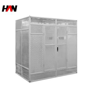
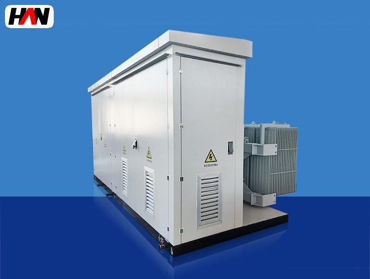
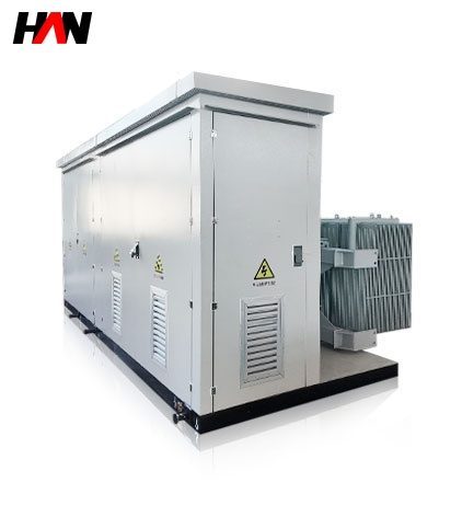
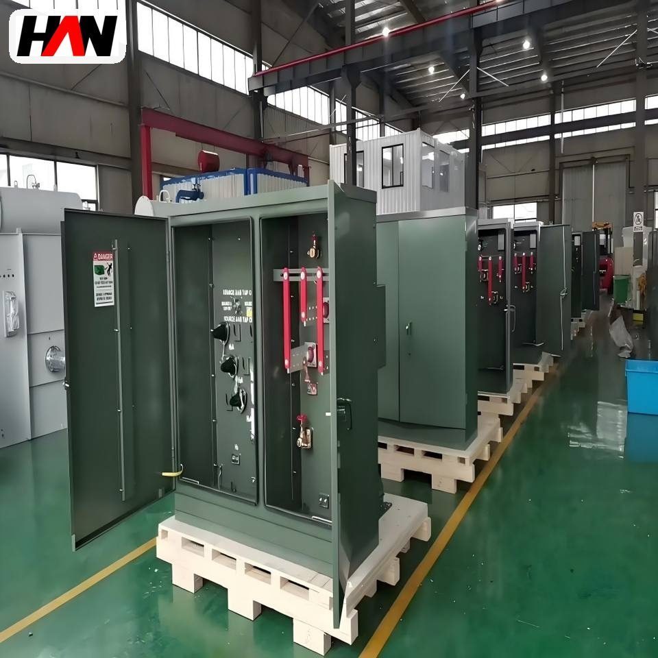
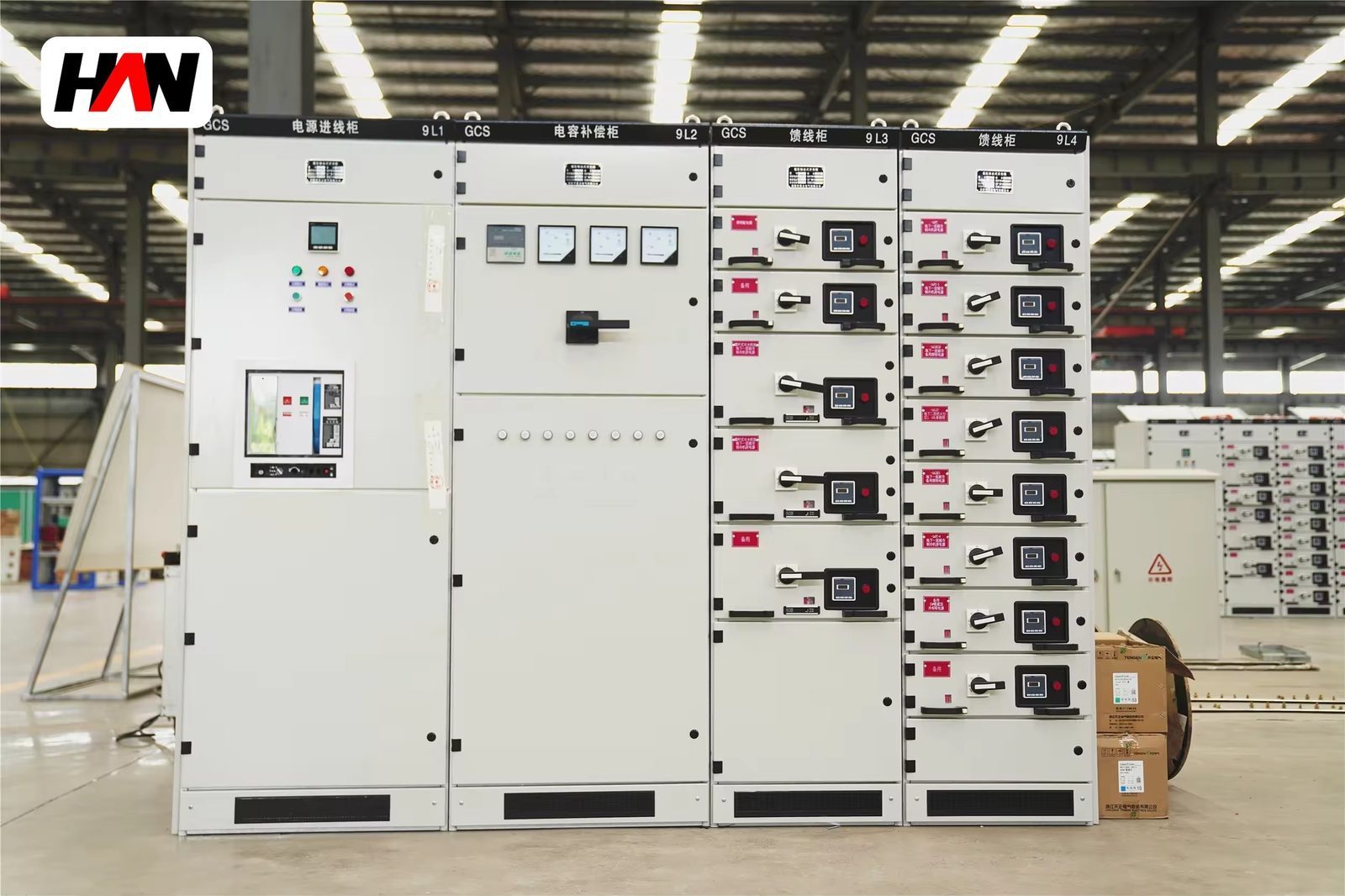
A prefabricated substation for an EAF project is a complete electrical room built on a steel skid. Medium-voltage switchgear, a distribution transformer and the low-voltage distribution board are mounted, wired and tested in the factory, then shipped as one transport unit and set down on a prepared foundation at site. The site work is reduced to connecting the incoming medium-voltage cable, the outgoing low-voltage feeders, the earthing conductor and the control signals, followed by commissioning tests. HANI Metallurgy builds these units for 10 kV and 35 kV systems with transformers from 630 to 2500 kVA, to IEC 62271-202 for the enclosure and IEC 61439 for the distribution assemblies.
The value of the format appears in the schedule of a new melt shop or a capacity expansion. A civil electrical house has to be designed, permitted, built, roofed and dried before the switchgear can be installed, and the switchgear then waits for the building while the furnace erection moves ahead. A skid-mounted unit is assembled in parallel with the civil works, tested under factory conditions where the test equipment and the skilled fitters are, and delivered when the foundation is ready. That is why the format is used for the auxiliary supply of an EAF transformer installation: the high-current furnace circuit itself is a separate design problem, but the medium-voltage and low-voltage distribution around it is a repeatable one.
Technical Parameters
| Parameter | Unit | 630 kVA | 1250 kVA | 2500 kVA |
|---|---|---|---|---|
| Transformer capacity | kVA | 630 | 1250 | 2500 |
| Medium-voltage supply | kV | 10 | 10 / 35 | 35 |
| Low-voltage output | V | 400 | 400 / 690 | 400 / 690 |
| MV switchgear | — | ring main unit | withdrawable cubicles | withdrawable cubicles |
| LV distribution | — | fixed, 6 – 10 ways | withdrawable, 10 – 16 ways | withdrawable, 16 – 24 ways |
| Structure and protection | — | steel skid base, container-style body, overcurrent and earth fault protection | ||
| Protection degree | IP | IP23D – IP54 | ||
| Transport | — | one unit on skid, four-point lifting, road or sea | ||
| Site work | — | incoming and outgoing connections, earthing, commissioning tests | ||
| Design standard | — | IEC 62271-202, IEC 61439 | ||
Typical values for reference. Final rating, way count and transport dimensions are confirmed on the outline drawing and the approved project datasheet.
How It Works Under Furnace Duty
The internal layout follows a service sequence rather than a drawing convenience. The medium-voltage cubicles are grouped at one end, reached from a front corridor, so a breaker can be racked out without passing the transformer. The transformer room sits behind a steel bulkhead with its own louver and its own heat path. The low-voltage board faces the opposite end, with the outgoing cables leaving through a floor gland plate into a trench. Everything that needs to be touched weekly is on the corridor side; everything that needs to be touched once a year is behind a bolted panel. That discipline is what makes a prefabricated unit maintainable rather than merely compact.
Under EAF duty the auxiliary supply is not a quiet load. The dedusting fans start in sequence and draw a starting current several times their running current; the water pumps run continuously; the hydraulic power unit cycles; and the whole auxiliary board sees the voltage dips that the furnace puts on the plant busbar during bore-in. Two consequences follow. The first is that the transformer for the auxiliary board is chosen with a thermal margin and with a short-circuit impedance that keeps the low-voltage fault level within what the board can withstand. The second is that the protection settings have to ride through a voltage dip without tripping the whole auxiliary board, because a fan trip during melting is a furnace stop, not a nuisance alarm.
The mechanical side of a skid unit carries its own engineering. The base frame is stiff enough to be lifted at four points without twisting the enclosure, because a twisted body opens door gaps and destroys the IP rating on the first lift. The transformer is resiliently mounted on the skid and its tank is bonded to the frame, so vibration from the fans and from the furnace building does not reach the switchgear. Cables and busbars are factory-formed and labelled, so the site electrician terminates instead of fabricating, which removes the most common source of a commissioning delay.
Engineering notes
1. Transport dimensions decide the design, not the other way round; agree the shipping envelope before the internal layout is fixed.
2. A skid unit is heavier at one end; mark the centre of gravity on the frame and give the crane operator the lifting plan with the drawing.
3. Leave a spare way and a spare cubicle position. An EAF project always adds a load after the furnace is commissioned.
Key Advantages
- Factory wiring, site connection: cables, busbars and interlocks are made and tested in the workshop, so site work is limited to terminations, earthing and commissioning.
- Parallel with civil works: the unit is built while the foundation is being cast, which takes the electrical room off the critical path of a furnace project.
- One transport unit: a stiffened skid with four lifting points and marked centre of gravity keeps the enclosure square through lifting, road transport and sea freight.
- Service corridor inside: medium-voltage cubicles and the low-voltage board both face a walk-in corridor, so routine operation never requires entering the transformer room.
- Expandable by design: a spare cubicle position and spare low-voltage ways are reserved at the factory, so a later load addition does not need a second enclosure.
Selection and Commissioning
- Define the scope of the unit. Decide what travels on the skid: medium-voltage switchgear, transformer, low-voltage board, control panel, and where the interface with the plant control system sits.
- Agree the shipping envelope first. Weight, height and lifting points are fixed by the route to site; the internal layout is then designed inside that envelope.
- Fix the auxiliary load list with starting currents. Fan and pump starting currents, not running kilowatts, decide the transformer rating and the low-voltage breaker settings.
- Coordinate protection with the upstream feeder. The medium-voltage relay settings inside the unit must grade with the plant feeder protection, or a fault will trip the whole busbar instead of one unit.
- Prepare the foundation to the drawing. Flatness, cable openings, earthing connection points and drainage are checked before the unit is lifted off the truck.
- Commission in two stages. Factory acceptance tests before shipment, then insulation, relay injection, interlock and function tests at site, followed by a load run with the fans started in sequence.
Frequently Asked Questions
Q1: What limits the size of a prefabricated unit?
A: Transport, not electrical design. Road width, bridge clearances, the crane capacity at site and the lifting points on the frame set the maximum shipping weight and height. Above that limit the unit is split into two modules with a bolted joint and a site-made busbar connection.
Q2: How long does site work take?
A: The work is connection and testing rather than construction: setting the unit on the foundation, terminating the incoming and outgoing cables, bonding the earthing, then insulation, relay and function tests. The duration depends mainly on the number of outgoing feeders and on how many cables are already pulled to the trench.
Q3: Can the unit be expanded later?
A: Yes, if the expansion is planned at the design stage: a spare cubicle position in the medium-voltage room, spare low-voltage ways and a reserve in the transformer rating. A unit built without that reserve can usually only be expanded by adding a second enclosure beside it.
Q4: How does the cost compare with a civil substation building?
A: The enclosure itself usually costs more than the walls of a simple building. The comparison turns on schedule and on site labour: factory assembly, factory testing and a short site programme normally offset the higher material cost, and the difference narrows further where site labour is scarce or the plant is far from a fabrication base.
Take the Electrical Room Off the Critical Path
Send the auxiliary load list, the supply voltage, the transport route and the foundation drawing, and HANI Metallurgy will return a skid layout, a scope split and a factory test plan.