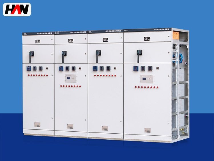
Description
Reactive Power Compensation
Power factor, harmonics and flicker control
Overview
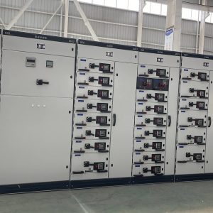
Reactive power compensation is the equipment that supplies the magnetising and arc-reactive demand of a melt shop locally, instead of dragging it from the utility through the plant transformer. In a plant with an electric arc furnace the need is not a single problem but three: a low power factor that is billed every month, a harmonic spectrum produced by the arc itself, and a voltage fluctuation that shows up as flicker on the plant busbar and on the feeder to the neighbouring works. HANI Metallurgy supplies two layers of equipment that address the first two of these — low-voltage automatic capacitor banks from 50 to 600 kvar per lineup with series reactors, and medium-voltage filter branches on the furnace transformer bus.
The distinction matters because the two layers are frequently confused in a tender. A low-voltage bank switched by contactors or thyristors sits at 400 V and corrects the auxiliary load: fans, pumps, compressors, conveyors, lighting and the workshop distribution. It cannot follow an arc furnace, because the furnace does not draw its reactive power at 400 V — it draws it at the transformer primary, and its current swings within a single heat. Correction at that level is done on the medium-voltage side with filter branches tuned to the harmonic orders that the arc produces.
Technical Parameters
| Parameter | Unit | 150 kvar | 300 kvar | 600 kvar |
|---|---|---|---|---|
| Compensation per lineup | kvar | 150 | 300 | 600 |
| Rated voltage | V | 400 | 400 | 400 |
| Steps | steps | 6 | 8 | 12 |
| Step size | kvar | 25 | 40 | 50 |
| Detuning reactor | % | 7 or 14 | 7 or 14 | 7 or 14 |
| Switching device | — | contactor | contactor / thyristor | thyristor |
| Response | — | step by step, with discharge delay | cycle-level, thyristor | cycle-level, thyristor |
| Step protection | — | fuse per step, overvoltage and unbalance trip | ||
| Target power factor | — | 0.95+ | 0.95+ | 0.95+ |
| Design standard | — | IEC 60831, IEC 61921 | ||
Typical values for reference. Final step schedule, reactor factor and protection settings are confirmed on the approved project datasheet.
How It Works Under Furnace Duty
An arc furnace is an impact load with a bad harmonic signature. During bore-in and melting the arc length changes from cycle to cycle, so the current drawn from the supply swings with it; the reactive component of that current depresses the busbar voltage, and the depression repeats at the rhythm of the arc, which is what the neighbours see as flicker. The same non-linear arc produces harmonic currents, predominantly of the low orders, that flow back into the plant network and into the utility feeder. A capacitor bank connected to such a network is not a passive corrector: it is a parallel resonant circuit with the source inductance, and if its resonant frequency happens to coincide with a harmonic the arc produces, the harmonic current will be amplified rather than filtered.
That is the reason every HANI bank is supplied with a series reactor. A 7 % reactor moves the resonant frequency of the branch below the lowest harmonic that needs to be avoided in a typical melt shop network, so the branch behaves inductively at that order and cannot amplify it. A 14 % reactor shifts the branch further down and is used where the lower order content is dominant or where the network is weak. The reactor costs a small part of the reactive output of the bank, because the capacitor has to be rated for a higher voltage to deliver the same kvar through the reactor, and it is the reason an unfiltered bank is cheaper on paper and more expensive in service.
Switching is the third design point. A capacitor draws a very large inrush current at the instant of energisation, limited only by the impedance between it and the network, and the inrush is worse when a step is switched in parallel with a step that is already energised. Capacitor-duty contactors with damping resistors, or thyristor switches that close at the voltage zero crossing, keep that current within what the capacitor and the fuse can take. Thyristor switching also removes the waiting time between a disconnection and the next reconnection, which matters on a load that changes every few seconds.
Engineering notes
1. A detuned bank is not a filter. It avoids amplification; removing a specific harmonic order needs a tuned branch on the medium-voltage side.
2. Capacitor case temperature, not bank current, is the first sign of a harmonic problem; a hot case with a normal current reading means the spectrum has changed.
3. Never correct the furnace itself at low voltage. The reactive current of the arc never passes through the 400 V board, so a low-voltage bank will not move the furnace power factor.
Key Advantages
- Series reactor as standard: every step is supplied with a 7 % or 14 % reactor and a capacitor rated for the resulting voltage, so the branch is safe on a network with arc harmonics from the first day of operation.
- Step resolution matched to the load: six to twelve steps of 25 to 50 kvar keep the correction close to the demand instead of swinging between over-correction and a lagging penalty.
- Contactor or thyristor: the same lineup can be built with damped contactors for a steady auxiliary load or with thyristor switches for a load that changes every few seconds.
- Protection at step level: a fuse per step, plus overvoltage and current unbalance trips, isolates a failed capacitor instead of taking the lineup out and leaving the plant at a low power factor.
- Designed alongside the furnace transformer: reactor factor, step size and target power factor are fixed together with the EAF transformer impedance, so the two do not fight each other.
Selection and Commissioning
- Separate the two loads. Meter the auxiliary 400 V load and the furnace feeder independently; the first gives the low-voltage bank size, the second shows what has to be handled at medium voltage.
- Measure the spectrum before choosing a reactor. A short power quality survey on the busbar decides between 7 % and 14 %, and shows whether a tuned branch is required at all.
- Size for the target, not for unity. Aim at 0.95 or slightly above; correction beyond that leaves the plant exposed to overvoltage when the load drops at the end of a heat.
- Check the capacitor voltage rating. The capacitor must be rated above the system voltage because it sits behind a reactor; a standard 400 V can in a detuned branch is a short service life.
- Plan the ventilation of the room. Capacitor losses and reactor losses both end up as heat; a bank in a closed electrical room needs an air path, not just a door.
- Commission with a load sweep. Log power factor and step sequence through a full heat, confirm that no step hunts, and record the harmonic spectrum again so the as-built condition is documented.
Frequently Asked Questions
Q1: Why does every step need a reactor?
A: Because a capacitor without a reactor forms a resonant circuit with the source inductance at a frequency that a melt shop network will excite. The reactor shifts that resonance below the harmonic range of interest, so the bank stays inductive at the orders the arc produces and does not amplify them.
Q2: Why do capacitor banks burn out in furnace plants?
A: Almost always through harmonic overcurrent and overvoltage, not through old age. The capacitor is the lowest impedance path in the network at harmonic frequencies, so it absorbs current it was never rated for; the case temperature rises, the dielectric degrades, and the fuse clears a step that could have been protected by a reactor and a correct voltage rating.
Q3: How is the compensation capacity decided?
A: From the reactive demand at the point of connection and the power factor the utility requires, measured over a representative production period. The bank is then split into steps so that it can follow the load without overshooting, and the reactor factor is chosen from the measured harmonic spectrum.
Q4: Can a low-voltage bank improve the power factor of the furnace itself?
A: No. The reactive current of the arc is drawn at the furnace transformer primary and never reaches the 400 V board, so a low-voltage bank corrects only the auxiliary load. The furnace contribution has to be handled at medium voltage, on the furnace transformer bus, by equipment sized for that duty.
Correct the Load, Not the Bill
Send the auxiliary load list, the furnace transformer rating and a harmonic survey if one exists, and HANI Metallurgy will propose a step schedule, a reactor factor and a protection arrangement.